

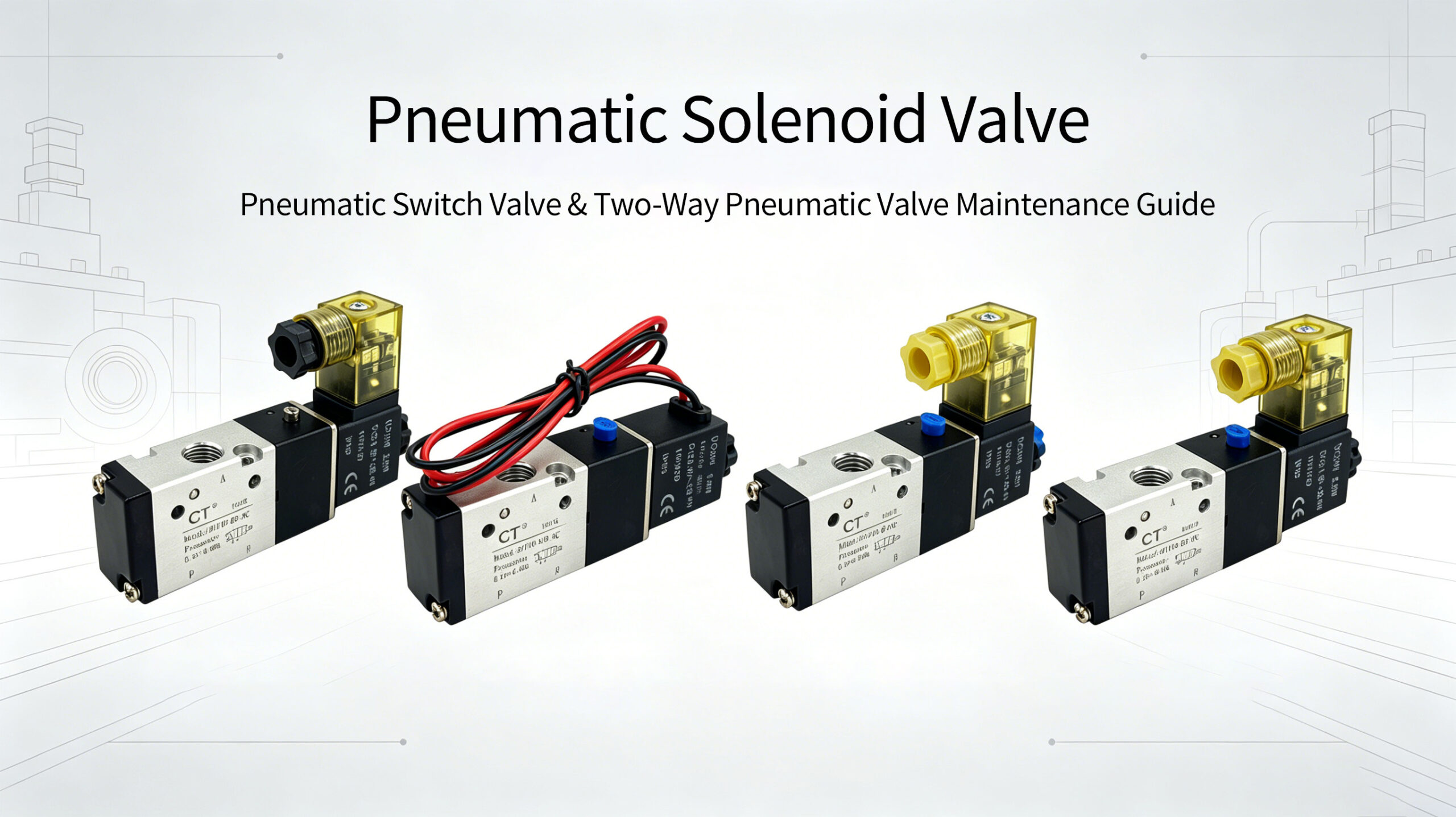
Two‑Way Pneumatic Solenoid Valve Reliable| Pneumatic Switch Valve & Two‑Way Pneumatic Valve Maintenance Guide
Two‑Way Pneumatic Solenoid Valve are widely used control valves. Their reliability and stability greatly affect the normal operation of the whole pneumatic system. Below are practical methods to improve the reliability and stability of pneumatic solenoid valves, pneumatic switch valves and Pneumatic Two‑Way Directional Control Valve
When selecting a two‑way pneumatic solenoid valve, you shall fully consider working environment, pressure, flow rate and other key factors. For high‑temperature working conditions, high‑temperature resistant models are recommended; for high‑pressure applications, high‑pressure resistant two‑way pneumatic valves are required. Brand and quality should never be ignored. Reliable and high‑quality pneumatic switch valves can ensure stable long‑term operation.
Key notes for installing two‑way pneumatic solenoid valves:
- Install the valve properly to avoid vibration and impact damage.
- Ensure correct wiring to prevent component damage caused by wiring errors.
- Keep the air passage unobstructed to avoid blockage‑related malfunctions.
Common rated voltages for solenoid coils include DC12V, DC24V, AC24V (50/60Hz), AC110V (50/60Hz), AC220V (50/60Hz) and AC380V (50/60Hz).
Two mainstream options are widely adopted in electrical design:
- AC220V: No switching power supply required, featuring low cost, simple wiring and easy maintenance.
- DC24V: Safe extra‑low voltage, with convenient replacement for switching power supplies and solenoid coils.
Quality Inspection for Pneumatic Solenoid Valves
Feed pressurized liquid or gas medium within the valve’s operating pressure range (medium pressure at intermediate value), then energize the coil. If the medium shows obvious on‑off switching, the pneumatic solenoid valve works normally; otherwise, it is faulty.
Common Malfunctions & Troubleshooting
1. Short‑Circuited or Open‑Circuited Coil
Inspection: Measure coil continuity with a multimeter. Near‑zero or infinite resistance indicates short‑circuit or open‑circuit fault. Note that normal resistance (about tens of ohms) cannot fully guarantee coil integrity. For instance, a coil with 50Ω resistance may still fail to drive the valve even with normal resistance reading, which can only be confirmed by further magnetic test.
Place a small screwdriver near the metal core inside the coil, then energize the coil. Magnetic force indicates a functional coil; no magnetic force means coil damage.
Solution: Replace the solenoid coil.
2. Faulty Plug & Socket
For plug‑type pneumatic switch valves, malfunctions often result from damaged socket springs or wrong wiring (e.g. live wire connected to ground wire), leading to power failure of the coil.
Always fasten plug fixing screws and coil fixing nuts firmly after installation.
For DC‑powered coils with LED power indicators, correct polarity is required; reversed polarity will disable the indicator. Do not mix plugs with different voltage ratings, as it may burn out LEDs or cause short‑circuit. Polarity is not required for coils without LED indicators.
Solution: Check wiring, repair or replace plugs and sockets.
3. Spool Malfunction
Fault 1: Under normal medium pressure, pressing the manual red button shows no medium on‑off change, indicating a faulty spool.
Check medium quality first, such as excessive condensed water in compressed air (often caused by poor pipeline design or ineffective oil‑water separators) or impurities in liquid medium. Clean water and impurities inside the valve and pipeline. Replace or repair the spool if the issue persists; replace the whole two‑way pneumatic valve when necessary.
Fault 2: The original matched coil generates normal magnetic force when energized, yet the valve fails to act normally (manual button may work properly). This is also a spool‑related fault.




Add comment