

Application, Principle and Selection Analysis of Cylinder Magnetic Switches in Automated Assembly Lines
Table of Contents
- 1. Core Working Principle of Cylinder Magnetic Switches
- 2. Selection Basis and Practical Experience of Magnetic Switches for Automated Assembly Lines
- 3. Application Value of Magnetic Switches in Automated Assembly Lines
Modern automated assembly lines adopt pneumatic actuators for core processes including material handling, product sorting and workpiece assembly. These actuators feature simple structures, low costs, rapid response and easy maintenance.As the core executive components of pneumatic systems, cylinders determine the operational stability and production accuracy of the entire assembly line through the precision of their stretching, pushing, clamping and resetting movements. As a core position detection sensor matched with cylinders, magnetic switches are key components for realizing closed-loop automatic control of cylinder movements. They can accurately feed back the working status of cylinders and provide core signal basis for PLC (Programmable Logic Controller) logic operation, process linkage and action switching, which serves as an important foundation for ensuring the orderly connection of each process and safe and stable operation of equipment on assembly lines.
In the automated assembly line project practiced in this work, the material handling mechanism equipped on the assembly line features four-degree-of-freedom motion, enabling four core movements: arm stretching, arm rotation, parallel jaw gripper opening and closing, and gripper lifting and lowering. Two-way electrically controlled solenoid valves drive and regulate all pneumatic motions to deliver automatic and standardized operation. Meanwhile, technicians fit standard magnetic switches onto every functional cylinder at the assembly line’s material sorting stations. These switches fully address issues including failed automatic position detection for cylinder motions, lack of signal feedback for process coordination and inadequate equipment linkage precision.
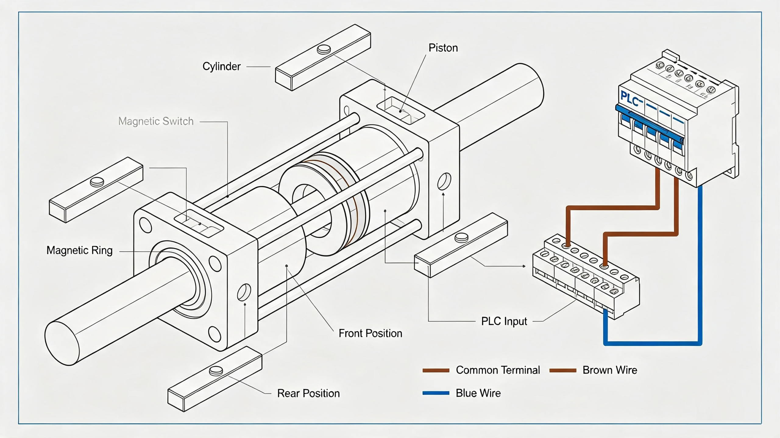
To realize accurate full-stroke position monitoring of cylinders, the general industrial installation specification is to fix one magnetic switch at the front end and one at the rear end of each cylinder, corresponding to the two limit working positions of full extension and full retraction respectively. During equipment operation, the magnetic switches collect the real-time position signals of the cylinder piston. Once the cylinder is detected to reach the preset position accurately, the switches immediately output switching signals and transmit them to the PLC control system. After receiving the signals, the PLC judges the completion of the current cylinder action according to the preset control program, and then triggers the action of the next process, so as to realize automatic linkage and orderly switching of each station on the assembly line. This effectively avoids equipment failures and production errors such as advance action of incompletely extended/retracted cylinders, process dislocation and material sorting mistakes. This project mainly employs the D-C73 magnetic switch. As a standard two-wire sensor, it follows clear wiring rules: route the brown signal wire to the PLC input terminal and run the blue wire to the input signal common terminal. Adapted to the industrial universal DC24V control circuit, it can stably and accurately convert the cylinder in-place state into electrical signals, realizing real-time visual and digital monitoring of cylinder working status.
1. Core Working Principle of Cylinder Magnetic Switches
Magnetic switches realize non-contact position detection mainly based on the magnetic induction principle and the structural characteristics of cylinders. The detection process involves no mechanical contact or wear, with fast response speed and long service life, making it suitable for the high-frequency and continuous operation scenarios of assembly lines.
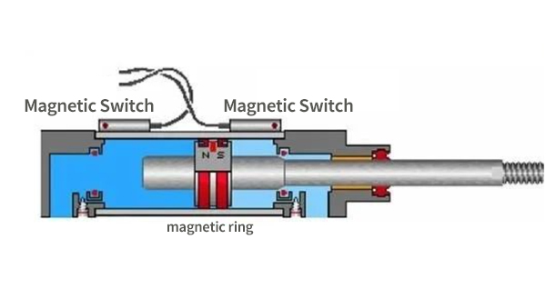
The cylinder barrels used in industrial automation are generally made of weakly magnetic and highly magnetically permeable materials such as aluminum alloy and stainless steel. These materials will not shield the internal magnetic field of cylinders, ensure the detection sensitivity of external magnetic switches, and meet the equipment requirements of light weight, corrosion resistance and wear resistance. An annular magnetic ring is integrally fixed on the piston assembly inside the cylinder. The magnetic ring moves synchronously with the piston during stretching and resetting, forming a dynamic magnetic field outside the cylinder barrel that changes with the piston position, which provides a magnetic field signal source for the position detection of magnetic switches.
Magnetic switches are fixed in the standard mounting grooves on the outer side of cylinder barrels through special mounting structures, and their positions can be fine-tuned according to actual station requirements. When the piston drives the magnetic ring to move to the detection position corresponding to the magnetic switch, the magnetic field generated by the magnetic ring penetrates the thin-walled cylinder barrel and acts on the internal sensing elements of the magnetic switch. Triggered by the magnetic field, the internal circuit of the magnetic switch is conducted to output level signals; when the magnetic ring moves away from the magnetic switch along with the piston, the magnetic field disappears, the internal circuit is disconnected, and signal output stops.
In short, magnetic switches accurately judge the real-time position of the cylinder piston and capture the full extension and full retraction status of the cylinder by sensing the presence or absence of the magnetic field from the piston magnetic ring, so as to realize full-process monitoring of the cylinder stroke and working status. This non-contact detection method fully eliminates drawbacks found in traditional mechanical limit switches, including collision abrasion, frequent faults and sluggish response. It suits high-frequency reciprocating pneumatic operating conditions on automated assembly lines perfectly.
2. Selection Basis and Practical Experience of Magnetic Switches for Automated Assembly Lines
The selection of magnetic switches directly affects the cylinder control accuracy, PLC signal stability and the overall operational reliability of assembly lines. Engineers should avoid arbitrary universal selection. They need to comprehensively evaluate multiple factors: cylinder model, control circuit parameters, installation conditions and load equipment type. While assembling, commissioning and running the sorting and conveying equipment on this assembly line project, practitioners select three magnetic switch models, D-C73, D-A73 and D-C76, as cylinder limit sensors. These choices align with the functions, dimensions and control demands of cylinders at different stations to satisfy operating requirements of various working positions. Drawing on practical experience, we sort the key criteria for magnetic switch selection into the following five dimensions.
1. Matching Cylinder Model and Working Conditions
Different types of cylinders (mini cylinders, standard cylinders, thin cylinders, swing cylinders, etc.) differ in the size of mounting grooves, cylinder barrel diameter and stroke range, corresponding to different installation dimensions and sensing distances of magnetic switches. Select factory-matched switch models for the cylinder first. This practice secures stable mounting and precise sensing distance, prevents detection blind spots, false signal triggering, loose fitting and other faults, and ensures reliable position detection.
2.Matching Working Voltage Specifications
Industrial magnetic switches are divided into two mainstream specifications: DC low voltage and AC high voltage, commonly DC24V and AC220V. Among them, DC24V is the universal safety voltage for assembly line control circuits, adapted to PLC control systems and low-voltage pneumatic circuits; AC220V is mostly applicable to high-power cylinders and direct relay control circuits. The voltage specification must strictly match the equipment circuit voltage to avoid switch burnout, signal disorder and equipment runaway caused by voltage mismatch. The entire project adopts a DC24V power supply system, and the matched D-C73 magnetic switch is fully adapted to this voltage specification with extremely high operational stability.
3.Distinguishing Sensor Wire System Types
At present, industrial magnetic switches are mainly divided into two-wire and three-wire types. The two-wire type features simple structure, convenient wiring and low occupation of PLC input points, which is the mainstream choice for small and medium-sized cylinders on assembly lines. The three-wire type has stronger anti-interference capability of signals, including NPN and PNP output types, suitable for high-precision and complex working conditions with strong electromagnetic interference. The D-C73 type mainly used in this project adopts a two-wire design with simple wiring and convenient maintenance, which fully meets the conventional control requirements of sorting and handling cylinders on assembly lines.
4.Adapting to On-site Installation Forms
According to the cylinder structure and station space constraints, the installation forms of magnetic switches include direct groove installation, rail installation, strap installation and pull rod installation. Operators adopt direct groove mounting for standard cylinders equipped with standard mounting slots. This method delivers secure fitting and precise positioning, and serves as the primary mounting solution for equipment on this assembly line. Users apply rail mounting and strap mounting mostly for special-shaped cylinders lacking dedicated mounting slots and legacy equipment retrofits, while pull rod mounting fits long-stroke and large-bore cylinders. Engineers choose the mounting method based on station space and cylinder structure to secure the switch firmly, enable position adjustment and eliminate mounting interference.
5.Matching Back-end Load Equipment Types
Magnetic switches transmit output signals to downstream control equipment. Typical loads cover PLCs, relays, integrated circuits and solenoid valves. Various load equipment accepts signals under distinct parameters, so engineers must select compatible models purposefully. The D-C73, D-A73 and D-C76 magnetic switches used in this project are all optimized for PLC control systems, with stable signal output and high level matching. They can quickly respond to the signal acquisition logic of PLCs, effectively avoid signal delay, signal loss and false detection, and ensure the accuracy of assembly line process linkage.
3. Application Value of Magnetic Switches in Automated Assembly Lines
Although magnetic switches are small supporting components in the pneumatic control system of automated assembly lines, they undertake core functions of status monitoring, signal feedback, process linkage and safety protection. Through limit detection by dual switches at the front and rear ends, the completion of cylinder movements can be accurately determined to provide closed-loop feedback for PLC program execution, completely solving the problem of blind operation of pneumatic actions without feedback. On the one hand, it effectively avoids production failures such as material sorting errors, workpiece clamping falling off and mechanism collision interference caused by incomplete cylinder movement, and improves the operation accuracy and product qualification rate of assembly lines. On the other hand, it realizes continuous automatic equipment operation without manual status detection of cylinders, greatly improving production efficiency and reducing manual inspection costs.
Meanwhile, magnetic switches feature non-contact operation, low loss and long service life, which can adapt to the 24-hour continuous operation of assembly lines. With low equipment failure rate and simple later maintenance, they significantly reduce the operation and maintenance costs of assembly lines, making them indispensable core detection components in modern automated pneumatic control systems.




Add comment