

How to Select Magnetically Coupled Rodless Cylinders | CY Series Technical Handbook
Ⅰ. Basic Definition and Working Principle
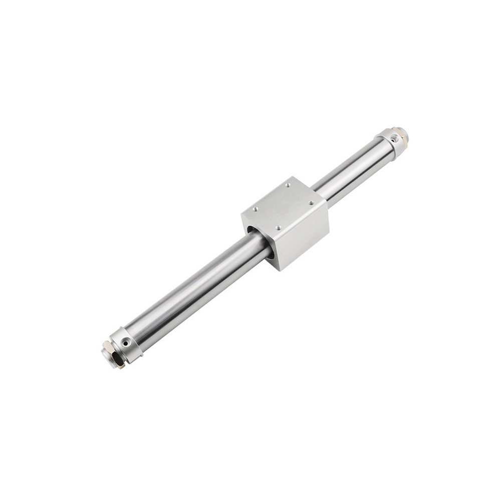
How to Select Magnetically Coupled Rodless Cylinders | CY Series Technical Handbook Magnetic coupling cylinder, full name magnetically coupled rodless cylinder, is a rodless linear cylinder. It transmits power through magnetic force across a gap. The mainstream models available on the market include CY1S, CY3B and DGO series.
Structural Composition
Barrel: Thin-walled non-magnetic aluminum alloy cylinder tube with full-length sealing, no slots and no extending piston rod.
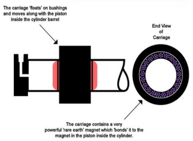
Built-in Piston: Embedded with high-strength NdFeB permanent magnetic rings.
External Slider: The outer sliding table is also fitted with magnetic rings of opposite magnetic poles.
Operating Principle
Compressed air drives the piston inside the cylinder to move. The two sets of internal and external permanent magnets attract each other across the cylinder wall, and the magnetic force drives the external slider to move synchronously with the piston. There is no direct contact between the piston and the slider, resulting in zero mechanical wear.
Core Advantages and Disadvantages
✅ Advantages
1.Saves 40%~50% axial space with compact mounting dimensions for long strokes.
2.Fully enclosed structure with zero air leakage and no oil/gas emission, achieving high cleanliness level.
3.No dynamic sealing rings, resulting in minimal friction, smooth operation and low noise; service life up to 50 million cycles.
4.The slider comes with built-in T-slots for easy mounting of tooling and sensors.
Risk of decoupling
1.If the load, lateral force or acceleration exceeds the magnetic force limit, the internal and external magnets will slip.
2.The slider will stop while the piston keeps moving.
3.Low rated load, not suitable for heavy-load working conditions.
4.The cylinder tube tends to sag under long strokes, so support guide rails need to be installed additionally.
Ⅱ. Complete Selection Steps (General for Mining & Assembly Line Applications)
1.Thrust Calculation Formula
Theoretical Thrust:F=P*πD^2/4
The conventional air supply pressure ranges from 0.4 to 0.6 MPa, with 0.5 MPa commonly used in factories.
2.Safety Selection Red Lines
1.Horizontal Handling: The cylinder output thrust shall be ≥ 1.3 times the total load (workpiece + slide table + fixture).
2.Vertical Lifting: The cylinder thrust shall be ≥ 1.8 times the total load.
3.High-speed Start/Stop & Reciprocating Impact: Reserve a safety margin of 2 times.
4.Special Requirement for Magnetically Coupled Cylinders: The actual load shall be ≤ 50% of the manufacturer’s rated decoupling force, with a safety factor of 2.0~2.5 to prevent slipping and position offset.
3.Stroke Selection
Stroke = Actual Travel Distance of Workpiece + Buffer Allowance at Both Ends (5~10 mm)
Standard strokes: 50/100/200/500/1000 mm
Extra-long strokes (>2000 mm): Intermediate support brackets must be installed to prevent magnetic attenuation and decoupling caused by cylinder tube sagging
For long-stroke applications, CY3 series with larger bore sizes is preferred for superior rigidity
4.Mounting Type & Guide Option Selection
1.Basic Standard Type CY1S: For general horizontal push-pull applications, no anti-rotation function, lateral force loading is prohibited.
2.Anti-rotation Type CY3R: Built-in guide structure prevents slider rotation, suitable for gripping tooling and visual inspection.
3.Guide Rail Integrated Type: Capable of heavy lateral loads. Equipped with linear guides, it greatly improves resistance to eccentric loads.
5.Cushioning & Magnetic Switches
Low speed & short stroke: Rubber cushioning
Medium/high speed & long stroke: Adjustable air cushioning for end deceleration and collision prevention
Magnetic switches: Standard for cylinders with magnetic rings; mounted in grooves to deliver position feedback signals. 3-wire NPN switches are compatible with PLCs.
6.Environmental Adaptability
Normal temperature general version: Standard aluminum cylinder barrel, -10~60℃
Humid & waterproof version: IP65 dustproof and waterproof model
High-temperature working condition: Adopts high-temperature resistant magnetic steel and seals, max. 120℃
Strong magnetic field workshop: Magnetically coupled cylinders are strictly prohibited. Magnetic interference will directly cause decoupling.
7. Output Force of Common Bore Sizes (0.5 MPa Air Supply)
φ16≈100N;φ20≈157N;φ25≈245N;φ32≈402N;φ40≈628N;φ50≈980N
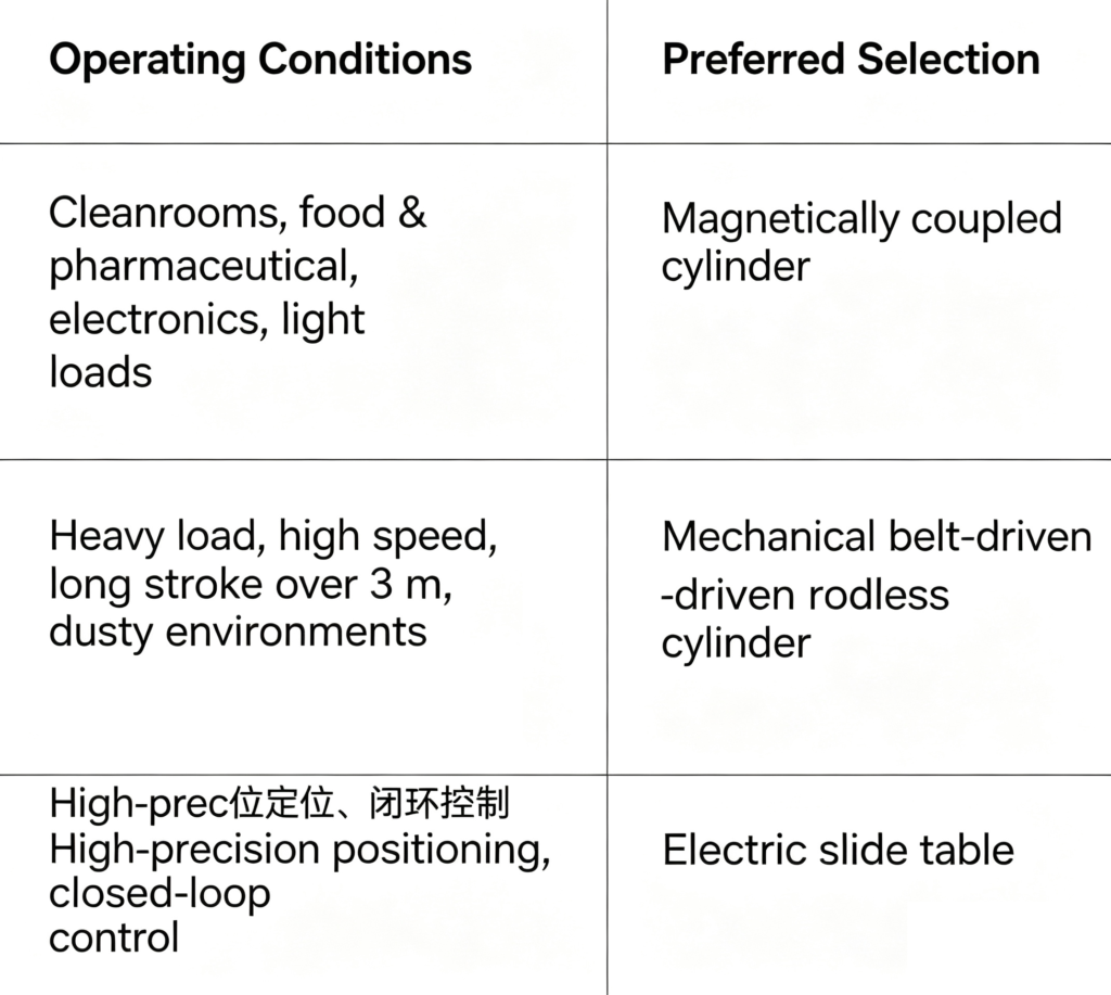
The maximum standard bore size for magnetically coupled cylinders is generally 63. For heavy loads, it is recommended to switch to belt-driven mechanical rodless cylinders.
Ⅲ. Typical Application Scenarios
1.Clean Production Lines for Electronics & Semiconductors
Wafer and PCB panel transfer. Oil and air leakage is strictly forbidden in cleanrooms, and the fully sealed structure of magnetically coupled cylinders offers an ideal fit.
2.Food & Pharmaceutical Packaging
Medication sorting, packaging bag opening and filling stations. Food-grade dustproof design prevents material contamination by oil residues.
3.Long-stroke Transfer for Automated Equipment
Sliding doors for windows, material fork translation in automated warehouses, reciprocating spraying mechanisms, and long-travel motion inside compact cabinets.
4.Printing & Lithium Battery Equipment
Cell handling, reciprocating motion for screen printing, long-stroke scanning of vision cameras; smooth operation without jitter.
5.Compact Precision Tooling
Dispensing modules, laser marking travel mechanisms, and reciprocating motion of inspection jigs.
Ⅳ. Key Points to Avoid Selection Pitfalls
1.Lateral Force Must Not Exceed Limit: Standard magnetically coupled cylinders can only withstand minimal lateral loads. Linear guides must be fitted if lateral load is high; otherwise, eccentric wear of the piston rod and magnet decoupling will occur.
2.Long-stroke Load Suspended Vertically Is Prohibited: Gravity will continuously weaken the magnetic coupling force and easily cause slippage.
3.Air Supply Pressure Shall Not Be Lower Than 0.4 MPa: Insufficient air pressure reduces thrust and may also lead to decoupling.
4.Intermediate Supports Are Mandatory for Strokes Over 1500 mm: Sagging cylinder barrels widen the gap between internal and external magnets, resulting in a sharp drop in magnetic force.
5.Recommended Maximum High-speed Operation: ≤500 mm/s. Excessive speed causes inertial impact that directly triggers decoupling.
How to Select Magnetically Coupled Rodless Cylinders | CY Series Technical Handbook

Add comment