

Pneumatic Valve Design Guide
Pneumatic Valve Design Guide,Directional control valves act as traffic commanders in pneumatic systems. They distribute, guide and reverse airflow to govern the movement of actuators. Before issuing a request for quotation, fluid power designers must first understand valve functions, flow rates (and sizing criteria), as well as construction materials suited to the application. This guide delivers practical insights to help you select the most appropriate directional control valve for your circuit and machinery.
Prioritize Circuit Design
Most pneumatic systems start with hand‑sketched layouts, followed by CAD schematic development. Designers add actuators, pressure valves, flow controls, auxiliary components and, of course, directional valves.
The operating characteristics of an actuator depend on whether a cylinder or pneumatic motor is deployed. Simple on‑off operations, such as a drill motor running continuously in one direction, only require a 2/2 valve to start and stop the drilling action.
Newcomers may comment: “But air flows in just one direction. Isn’t this a one‑way 2‑position valve?”
On the surface the observation holds true. In the early days of fluid power, engineers did not strictly define single‑direction flow. A “way” simply describes the number of ports built into a valve.
There is no need to label every directional valve on your bill of materials with verbose descriptions such as “2‑position, 2‑way bi‑directional valve”. Industry shorthand 2/2, 3/2, 4/2, 5/2 and 5/3 is widely accepted and concise.
If you are a hydraulic specialist new to pneumatics, the five ports of a 5‑way valve can seem confusing — this is not a typo.
Most pneumatic systems do not route exhausted air back to the centre position. Return exhaust circuits are only adopted for clean‑room applications such as semiconductors, pharmaceuticals and food & beverage production. Standard pneumatic valves vent exhaust directly to atmosphere, requiring one or two extra exhaust ports.
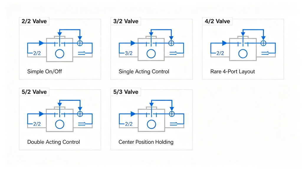
Below are the five most common pneumatic spool valve configurations
1.2/2 Valves (2‑Position, 2‑Way)
The simplest, most reliable and versatile option. When paired with spring or gravity return, a 2/2 valve controls single‑acting cylinders by cutting off supply air to enable retraction. It also serves widely as an auxiliary component, for example as a relief valve to eliminate trapped line pressure, or to generate pilot signals that actuate other main valves.
2.3/2 Valves (2‑Position, 3‑Way)
This valve delivers classic directional control performance. Before actuation, air flows out of port 2 while port 3 remains blocked. Once the valve shifts, inlet port 1 feeds air to port 2 and port 3 opens for exhaust.
It is ideal for single‑acting cylinders: the cylinder stays stationary until the valve energises to extend the rod, and resets automatically when the valve de‑energises
Design challenge: Try drafting a pneumatic circuit that replaces one 5/3 valve with two 3/2 valves
3.4/2 Valves (2‑Position, 4‑Way)
Visually similar to 3/2 valves but fitted with an extra working port marked port 4. Pneumatic valves follow ISO 5555‑1/2 standards: port 1 = supply pressure, ports 3 & 5 = exhaust, ports 2 & 4 = working outlets
4/2 valves are rarely used in modern pneumatic systems. A single exhaust chamber creates backpressure, and the design offers far less flexibility than a 5/2 valve. A 5/2 valve allows separate flow control fittings on each exhaust port for independent speed adjustment. Surviving 4/2 models are mostly outdated designs.
4.5/2 Valves (2‑Position, 5‑Way)
The first choice for double‑acting cylinders. Two independent exhaust paths enable flexible speed regulation, making it the most popular valve type for automated machinery.
5.5/3 Valves (3‑Position, 5‑Way)
Its standout feature is centre‑position holding. When the spool rests in the middle, all supply passages seal off, locking the cylinder mid‑stroke. Manufacturers offer three mainstream centre configurations:
✅ Exhaust centre (floating centre): Working ports connect to exhaust. The cylinder moves freely with no holding force.
✅ Pressure centre: The supply port stays connected to both working ports. This maintains stability for twin‑link cylinder setups and prevents piston drift caused by internal leakage.
The airflow arrows on the illustrated 5/3 valve indicate pilot operation. The vast majority of pneumatic valves adopt pilot actuation for good reason: pilot shifting is smoother and faster, while solenoid coil power consumption drops to only a few watts. Direct‑acting valves have become much harder to source. Many PLCs drive pilot solenoid coils directly without intermediate relays, simplifying wiring.
Sizing the Valve
Once you finalise your circuit layout and select a spool configuration, the next step is proper valve sizing. Pneumatic sizing differs greatly from hydraulic design because air is compressible. You must pay close attention to operating speed, cycle time, acceleration and energy consumption.
All manufacturers publish valve flow resistance as a Cv flow coefficient.
By definition, Cv describes how many US gallons of 60°F water pass through a valve with a pressure drop of only 1 psi. Water is incompressible while air is compressible, so treat Cv only as a preliminary guideline. Always cross‑reference manufacturer flow curves showing actual airflow at specific pressure differentials.
Avoid a common purchasing trap: do not judge a valve solely by a high Cv rating. Some valves boast impressive Cv figures yet perform poorly under pressure drop. If no flow curve is available and your operating point sits near the valve’s rated flow limit, select the next larger size for safety.
We will use a practical calculation example with a small cylinder to demonstrate flow estimation.
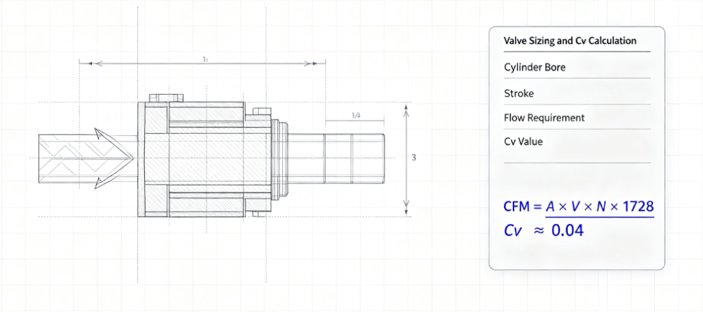
Cylinder bore: 2 inches, stroke: 8 inches, extend speed: 8 inches per second, shop supply pressure: 90 psi.
First calculate piston area and convert the required airflow into CFM (cubic feet per minute).
The result shows roughly 0.87 CFM is needed to reach the target speed. We add a 25–50 % flow margin to accommodate peak acceleration, bringing the practical requirement up to approximately 1.5 CFM.
You can fine‑tune slow speeds later by installing flow control valves, but insufficient valve flow capacity cannot be easily fixed after installation.
With the calculated airflow, we apply the formula to determine the required Cv value. The equation accounts for SCFM (standard cubic feet per minute), absolute temperature, gas specific gravity, inlet‑outlet pressure drop and atmospheric pressure.
Calculated under typical sea‑level room‑temperature conditions, with 90 psi supply and 10 psi pressure drop, the required Cv equals roughly 0.04. This proves even miniature directional valves deliver ample flow for such applications with plenty of spare capacity.
Select Valve Construction Style
After confirming flow sizing, choose the right mounting format. The three major categories are in‑line threaded valves, manifold‑mounted units and other modular series.
✅ In‑Line Threaded Valves
Cost‑effective and straightforward for actuator control. Only a small number of fittings are required for tubing and solenoid wiring.
No universal mounting base standard applies to in‑line valves. They cannot fit generic valve seats. Compact and simple to install, thread sizes range from 1/8 inch up to 1‑1/2 inch NPT. More spool and coil voltage options are available than standard ISO valves. Mechanical actuation types including cam, roller and foot pedal are optional.
NAMUR‑style valves resemble regular in‑line valves but incorporate an O‑ring sealed manifold interface on one side. They mount directly onto manifolds or custom actuators.
✅ ISO Standard Modular Valve Banks
These have dominated the market for decades. ISO 5599‑1/2 is the best‑known specification, identifiable by its rectangular mounting base with seven staggered oval port holes.
Modular ISO valves come in a full range of sizes with abundant functional options, and local distributors configure custom assemblies on demand. Manufacturers supply standard bases and stackable manifolds. Multiple valves bolt together and share a common main supply and exhaust line, drastically reducing piping work. Manifold plates accept add‑on modules such as throttle plates, pressure dump plates and integrated regulators, creating nearly endless combinations.
ISO 15407‑1 offers similar versatility in a slimmer, more compact body. Fewer size choices are available and most variants are compact, but the 1/4‑inch version achieves solid flow performance. Certain suppliers design manifolds compatible with both ISO 15407 and 5599 valves for mixed installation.
✅ Non‑Standard & Replica Specialty Valves
A further group follows de facto industry norms copied by multiple manufacturers rather than official specifications. This category includes metal‑seated poppet valves, aluminium safety shut‑off valves with large red knobs and pocket‑sized mini valves. Many successful valve designs from the past sixty years have been replicated widely; some copies do not retain original part numbers.
Designers enjoy access to a vast product library covering standard and custom solutions from micro units to heavy‑duty large valves. A suitable spool configuration exists for every actuator, and a wide selection of solenoid coils supports systems ranging from simple circuits to highly complex automated equipment.


Add comment