

80% Industrial Pneumatic Applications | PLC + Cylinder + Solenoid Valve
From Linkage Logic to Automatic Control System Design
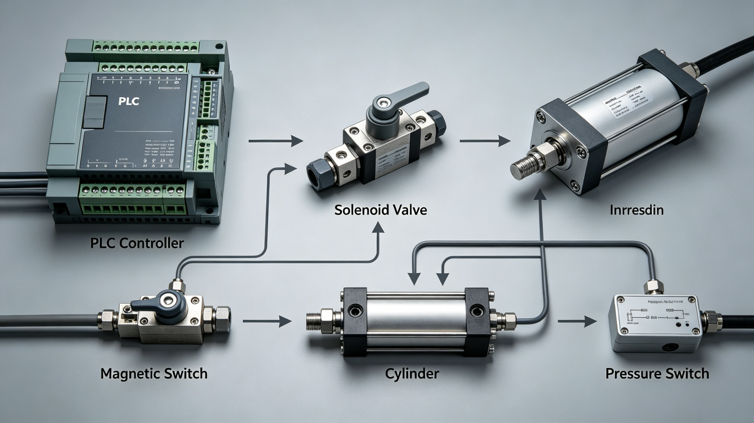
Master PLC Cylinder Control: Cover 80% Industrial Pneumatic Scenarios In industrial applications, the combination of cylinders and solenoid valves represents a classic pairing in terms of linkage logic and automatic control system design. Control signals transmitted by PLCs act as nerves delivering commands to equipment. Solenoid valves switch air circuits and function as control switches, while cylinders serve as mechanical actuators that perform physical reciprocating motions. Starting with the working principles and common classifications of cylinders, this article comprehensively outlines the design approach for a cylinder-based automatic control system.
1. Working Principles and Classification of Cylinders
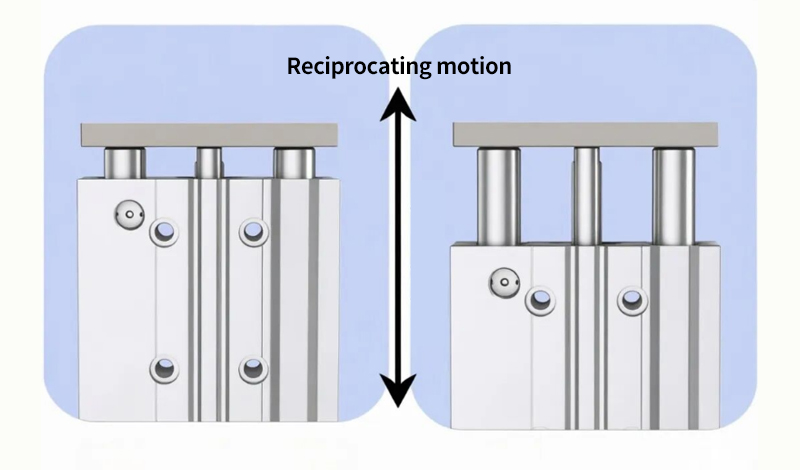
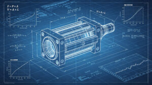
1. Working Principles A cylinder is a pneumatic actuator that converts the pressure energy of compressed air into mechanical energy. Its basic principle follows the classical mechanics formula: F = P × A (where F stands for output force, P for air supply pressure, and A for the effective area of the piston).
When compressed air enters the rodless chamber of the cylinder, it pushes the piston toward the rod chamber to complete the extending stroke. Conversely, the piston retracts.
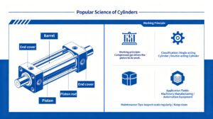
A standard cylinder mainly consists of the following components: cylinder barrel, piston, piston rod, front end cover, rear end cover, sealing rings and magnetic ring (for detection by magnetic switches). The magnetic ring is a permanent magnet ring mounted on the piston. It enables external magnetic switches to detect the piston position, and is a core component for cylinder position feedback.
Single-acting Cylinder
It has a single air port. Compressed air drives the piston to extend in one direction, while return motion relies on spring force or self-weight. Featuring simple structure and low air consumption, it is limited by spring resistance in output force and generally has a short stroke (≤100 mm). It is widely used for simple operations such as clamping and lifting.
Double-acting Cylinder
Equipped with two air ports, it is driven by compressed air for both extension and retraction. As the most commonly used type in industry, it delivers stable output force with a wide range of optional strokes (10 mm to 1000 mm and above).
Rodless Cylinder
It is divided into magnetic coupled type and mechanical contact type. With no exposed piston rod, it drives the slide block via magnetic force or mechanical structure. It requires minimal installation space, ideal for long-stroke material transfer and pushing in narrow spaces.
Rotary Cylinder
It converts pneumatic pressure energy into rotational motion, suitable for workpiece flipping, positioning rotation and station switching.
Guided / Sliding Table Cylinder
Built with an integral linear guide structure, its piston rod is free from lateral bending moment and features strong anti-eccentric load capacity. It applies to working conditions with lateral loads, including pressing, riveting and precise pushing of small parts.
Working Principles of Solenoid Valves
1. Basic Working Principles of Solenoid Valves
Solenoid valves are key components in pneumatic systems that control the flow direction, on-off state and flow rate of compressed air.
Working Principle:
When the solenoid coil is energized, the generated electromagnetic force overcomes the spring force and pushes the spool to shift, switching the on-off status of the air circuit. Once de-energized, the spool resets under spring force.
The model code of a solenoid valve generally includes two core parameters: position and way.
- Position: Refers to the number of working positions of the spool. A 2-position valve has two working positions, while a 3-position valve has three.
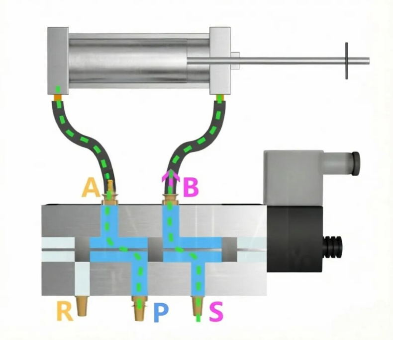
- Way: Refers to the number of air ports on the valve body. A 2-way valve has two ports (air inlet and outlet); a 3-way valve has three ports (inlet, outlet and exhaust); a 5-way valve is equipped with five ports: inlet P, outlet A, outlet B, exhaust R and exhaust S.
2. Comparison of Common Solenoid Valve Types
2/3 Way Solenoid Valve
Air ports: 3 ports
Applicable cylinder: Single-acting cylinder
Features: Simple structure with a single coil
Typical applications: Clamping, lifting
2/5 Way Solenoid Valve
Air ports: 5 ports
Applicable cylinder: Double-acting cylinder
Features: Most widely used type, controlled by a single coil
Typical applications: Material pushing, pressing assembly
3/5 Way Solenoid Valve
Air ports: 5 ports
Applicable cylinder: Double-acting cylinder
Features: With intermediate stop position, equipped with double coils
Typical applications: Position holding
3. Piping Connection between Cylinders and Solenoid Valves
1. Air Circuit Connection of Single-Acting Cylinders
A single-acting cylinder has only one air port, so it is matched with a 2/3 way solenoid valve.
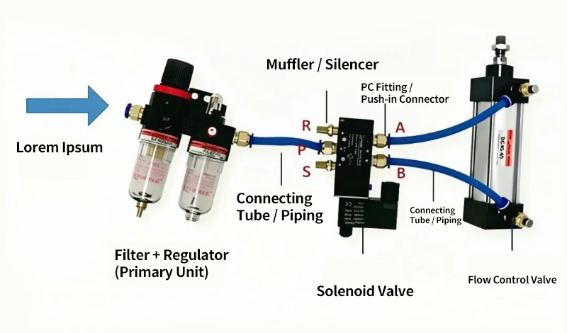
Connection method: The inlet port P of the solenoid valve is connected to the air supply (clean compressed air treated by pressure regulating valve and filter, with a pressure of 0.4~0.6 MPa), and the outlet port A is connected to the air port of the cylinder.
When the solenoid valve is energized, the passage from P to A opens and the cylinder extends. When de-energized, the passage from A to exhaust port R opens. The cylinder retracts under spring force, and compressed air is discharged through port R.
Master PLC Cylinder Control: Cover 80% Industrial Pneumatic Scenarios
2. Air Circuit Connection of Double-Acting Cylinders
A double-acting cylinder is fitted with one air port on the rod chamber and another on the rodless chamber. It is used with a 2/5 way or 3/5 way solenoid valve.
Standard connection method: Port P connects to the air supply, port A connects to the air port of the rodless chamber, and port B connects to the air port of the rod chamber. Port R and port S are each connected to an exhaust silencer.
4. Detection Principle and Wiring of Magnetic Switches
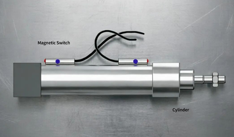
1. Working Principle of Magnetic Switches
A magnetic switch is a sensor that uses magnetic fields to control circuit on and off. When the permanent magnet mounted on the piston moves to the position of the magnetic switch, the magnetic field magnetizes and attracts the two reed contacts to close the circuit. As the piston moves away, the magnetic field disappears, and the contacts spring open by their own elasticity.
Key parameters of magnetic switches:
- Operating distance: Normally 5–10 mm; the actual installation clearance shall not exceed 8 mm.
- Load capacity: Generally ≤ 100 mA (DC) or ≤ 100 VA (AC). Never connect it directly to heavy loads. Signal conversion shall be implemented via PLC input terminals or relays.
- Output type: Divided into NPN type (low-level output) and PNP type (high-level output), which must match the interface type of the PLC input module. NPN type is commonly used for Japanese PLCs (e.g., Mitsubishi FX series), while PNP type is widely adopted for European PLCs (e.g., Siemens S7-1200).
2. Wiring of Magnetic Switches
Wiring type: Two-wire system
Wiring type: Three-wire system (DC)
3. In-position Detection Solutions for Cylinder Extension and Retraction
Fully extended detection: Mount a magnetic switch (extension limit switch) at the position where the piston reaches full extension. A triggered signal from the switch indicates the cylinder is fully extended.
Fully retracted detection: Install another magnetic switch (retraction limit switch) at the piston’s full retraction position. The activated signal means the cylinder has fully retracted.
Intermediate position detection: To detect intermediate positions (e.g., the midpoint of the stroke), fit a third magnetic switch at the designated spot to realize multi-point position detection.
Some high-end cylinders are equipped with analog position sensors such as magnetostrictive displacement sensors, enabling continuous full-stroke position detection with an accuracy up to 0.01 mm.
5. PLC Control Design Concept and Pressure Switch Control
1. Basic Logic of PLC-controlled Cylinders
Essentially, a PLC controls cylinders by switching the solenoid valve coils on and off via its digital output points. This changes the air circuit status to drive cylinder movements. Meanwhile, digital input points receive signals from magnetic switches to confirm the actual cylinder position, forming a closed-loop control system.
2. Programming Key Points
The complete control logic for a double-acting cylinder includes the following parts:
Extension Control Logic
When the Extend button is pressed or an extend command is received, and the cylinder is fully retracted (retraction magnetic switch activated), the extension solenoid coil is energized. The cylinder extends until the extension magnetic switch is triggered. A latching circuit is commonly used, with the in-position signal serving as the reset condition.
Retraction Control Logic
When the Retract button is pressed or a retract command is received, and the cylinder is fully extended (extension magnetic switch activated), the retraction solenoid coil is energized. The cylinder retracts until the retraction magnetic switch is triggered.
Interlock Protection
Interlocks must be installed for extension and retraction circuits to prohibit reverse movement during operation. This prevents simultaneous energization of two solenoid coils and resultant air circuit conflict, which is critical for double-coil valves.
Safety Considerations
Safety rules shall be followed in programming. For example, if the magnetic switch becomes loose or disconnected and loses signals, the power to solenoid valves shall be cut off automatically to avoid cylinder runaway. Signal timeout monitoring can also be added to the PLC program.
3. Pressure Switch Control
A pressure switch is not a direct drive component in pneumatic systems, but functions for logic judgment. It monitors the actual air pressure. When the pressure reaches the preset threshold, it converts the physical pressure signal into a digital signal and feeds it back to the control system (PLC or relay).
It ensures the cylinder delivers sufficient thrust before operation, or maintains stable clamping force after action, avoiding equipment malfunction or workpiece loosening caused by air pressure fluctuation.
Magnetic switches only detect positions. The combination of magnetic and pressure switches realizes dual confirmation of position + pressure:
- Safety Interlock (Prevent Virtual Clamping): After the cylinder moves into place, the system allows stamping only when the pressure reaches the set value. It triggers an alarm and locks all actions if the pressure is insufficient.
- Sequence Control: Pressure switches act as process triggers. Once the pressure of the previous cylinder meets requirements, the next solenoid valve is activated automatically, eliminating complicated timing programming.
Master PLC Cylinder Control: Cover 80% Industrial Pneumatic Scenarios


Add comment