

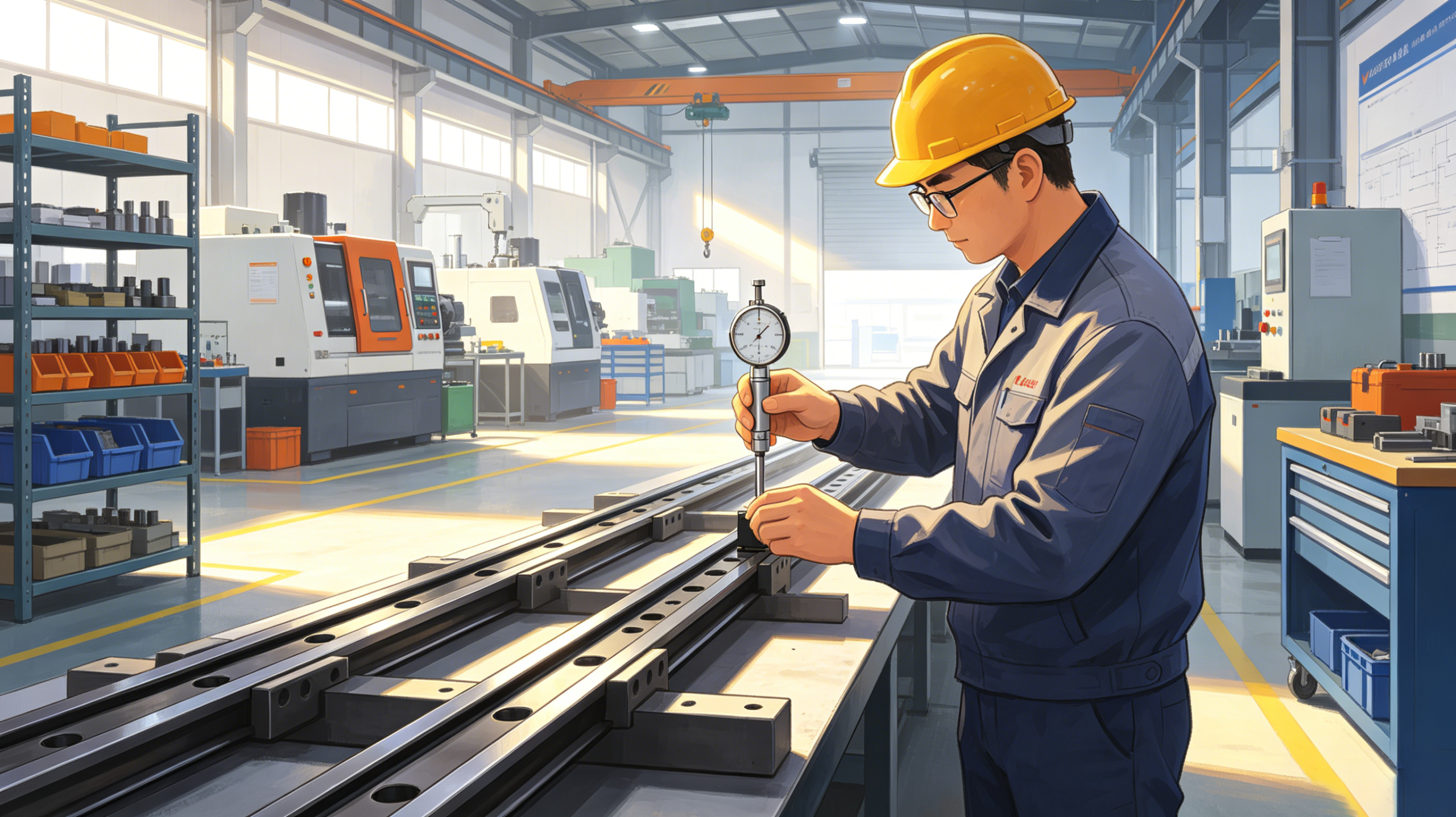
linear guide rail selection, linear guide installation guide, linear guide parallelism measurement
complete linear guide rail installation & precision testing guide
1.Main Classifications of Linear Guides
Rolling linear guides are the most widely adopted type in routine structural design, which are mainly divided into the following two major categories:
1.Ball Linear Guide (Most Commonly Used)
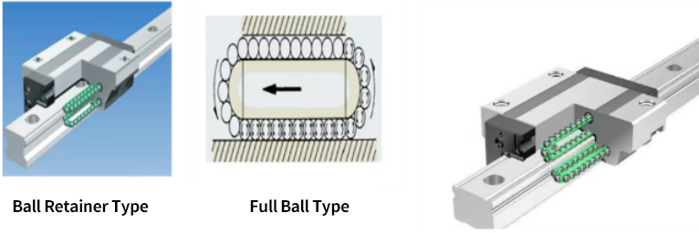
It uses steel balls as rolling elements and fits most conventional working scenarios, subdivided into two types:
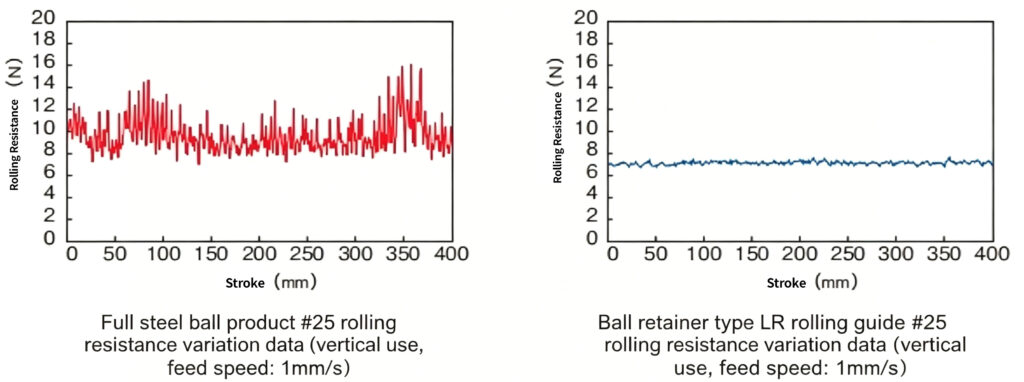
Ball Retainer Type: Steel balls are separated by a retainer to avoid mutual friction, which is the preferred option.
Full Ball Type: Steel balls are in direct contact with one another, causing friction and vibration during operation. Suitable for low-budget applications with low precision requirements.
2.Roller Linear Guide (For Heavy Load Applications)
It adopts rollers as rolling elements, featuring core strengths of high load capacity and high rigidity, yet higher cost than ball linear guides. It is subdivided into two types:
Roller Retainer Type: Rollers are evenly separated for smooth operation and stable resistance.
Full Roller Type: Rollers make direct contact with each other, leading to relatively greater resistance and wear, and are applied in fewer scenarios.
2. Core Advantages of Retainers
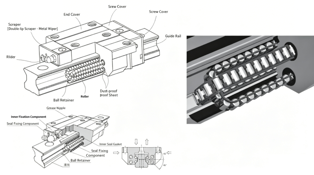
Whether it is ball linear guides or roller linear guides, models equipped with retainers are more practical than full-ball or full-roller types. Their main advantages are categorized as follows:
Five Major Advantages of Ball Retainers
No friction between steel balls, excellent grease retention, realizing long service life and long-term maintenance-free operation without frequent lubrication refilling.
Eliminate collision among balls to deliver low running noise and smooth sound performance, ideal for noise-sensitive equipment.
Low heat generation and outstanding high-speed performance, suitable for high-frequency operating conditions. Evenly arranged circulating steel balls ensure smooth movement without jamming.
Minimal wear, less grease splashing and low dust generation, perfectly compatible with clean working environments.
Four Major Advantages of Roller Retainers
Rollers are evenly separated to prevent offset, delivering stable rolling resistance and smoother movement.
Excellent lubricant retention enables long-term maintenance-free operation and reduces later maintenance costs.
Low heat generation with outstanding high-speed performance, ideal for high-speed and high-precision applications.
No collision between rollers, resulting in low noise and steadier operation.
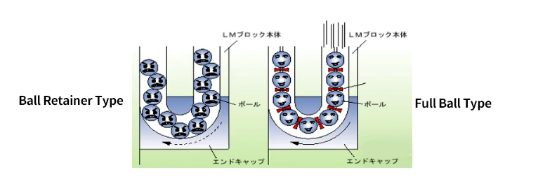
For full-ball linear guides, friction occurs between steel balls and causes vibration during operation. You can mount a dial indicator on the slider with its probe resting on a flat smooth surface, then pull the slider — the dial indicator needle will jump back and forth.In contrast, ball linear guides fitted with retainers operate far more smoothly. The retainer spaces each steel ball apart, and an oil film forms between them, making movement lighter and steadier than full-ball guides. (See the figure below for stability comparison.)
3.Adaptation for Special Environments: Selection Guidelines for Dust-Free, Vacuum, High & Low Temperature Conditions
Linear guides have vastly different requirements under various operating environments, especially special working conditions. Improper selection will drastically shorten service life. Focus on the following key points:
1.Dust-Free, Vacuum and Anti-Corrosion Environments
Stainless steel (martensitic or austenitic) is the top choice for its excellent corrosion resistance and rust-proof performance.
Surface Treatment
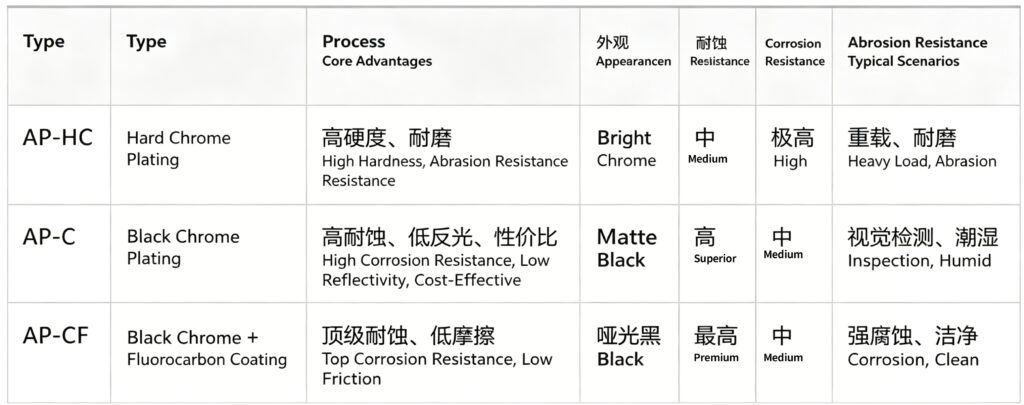
AP-CF (Black Chrome + Fluorocarbon Coating): Premium corrosion resistance and low friction, suitable for highly corrosive and cleanroom environments.
AP-C (Black Chrome Plating): Cost-effective option, ideal for humid and visual inspection applications.
AP-HC (Hard Chrome Plating): Outstanding wear resistance, designed for heavy-load scenarios.
Lubrication
For high-speed dust-free environments, use low-volatility greases including AFE-CA, AFF and L100 to minimize grease evaporation.
Fluorinated oil is adopted for vacuum conditions.
High-temperature grease is required in high-temperature environments to maintain stable rolling resistance.
Structure
Ball retainer type linear guides are mandatory, paired with slider dust covers to reduce dust generation.
2. High and Low Temperature Environments
Select linear guides with a low thermal expansion coefficient, which prevents significant dimensional variations caused by temperature fluctuations and maintains operational precision.
Comparison of Common Surface Treatment Processes
4.Standard Selection Process
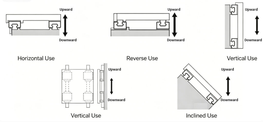
- Confirm the mounting method
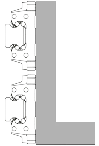
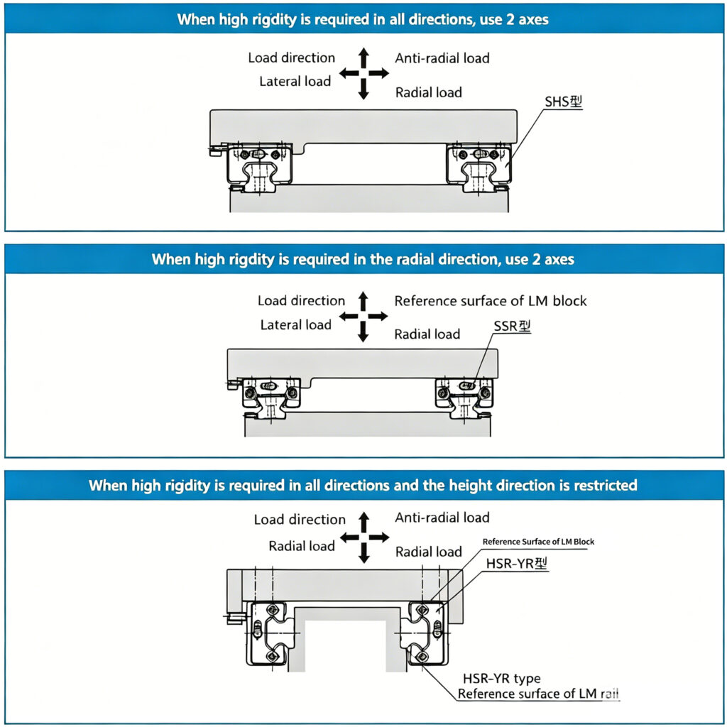
First clarify the mounting orientation of the linear guide (different mounting types are shown in the figure below). Since force conditions vary with each mounting method, select the corresponding guide type to match the actual working conditions.
2.Select Linear Guide Type
Linear guides generally feature two load-bearing forms: radial load and four-way equal load. The load conditions of the two types are shown below.
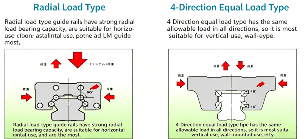
Radial Load Type (General Applications): SSR/SRS series are recommended, with the features listed below:
1. Long service life, enabling long-term maintenance-free operation
2. Low dust generation, low noise and smooth motion sound
3. Excellent high-speed performance
4. Smooth movement achievable under any mounting method
5. Lightweight and compact design
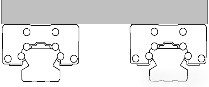
For wall-mounted and vertical installation: SHS series is recommended. It features 4-direction equal load with uniform force distribution in all directions and superior stability.
3. Load and Service Life Calculation
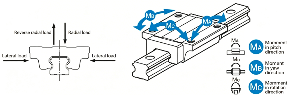
After determining the linear guide mounting type following the above process, calculate the load it bears and its service life based on the actual force conditions. First, you need to understand the forces acting on the guide in normal operation and their corresponding notation standards:
Lubrication and Dust Prevention Selection
Proper lubrication is mandatory. It reduces friction and wear, prevents rust, and extends rolling fatigue life. Different environments require matching lubricants, detailed as follows:
- For dust-free high-speed environments: Use low-volatility greases AFE-CA, AFF and L100 to minimize grease volatilization and environmental contamination during high-speed operation.
- For vacuum environments: Fluorinated oil shall be adopted as base oil to meet vacuum working conditions.
- For high-temperature environments: Special high-temperature grease is recommended to stabilize rolling resistance against temperature fluctuations.
- For standard general conditions: Low-viscosity spindle lubricating oil balances excellent lubrication performance and cost efficiency.
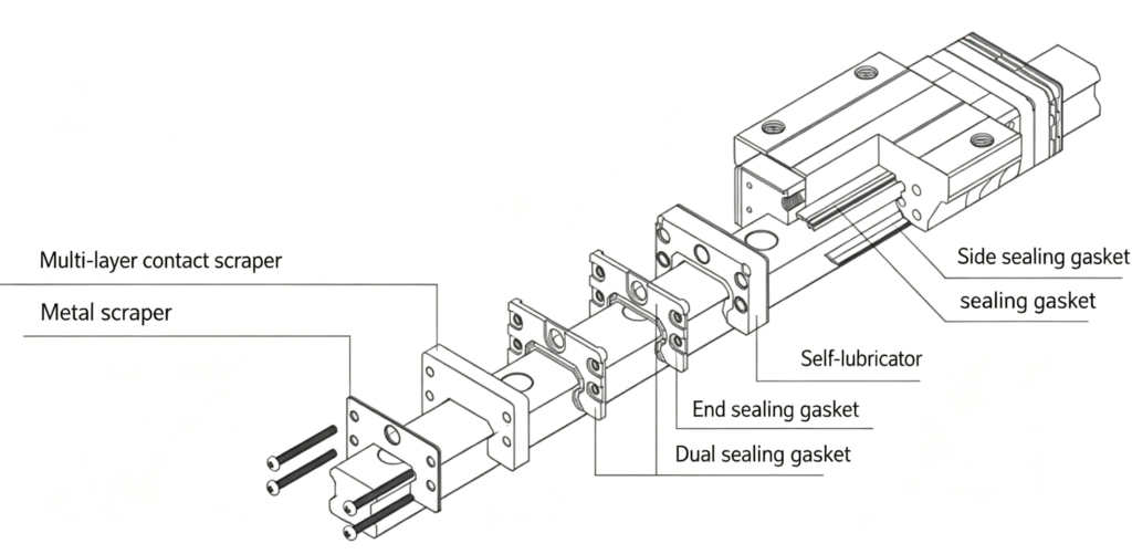
- Dust Prevention Different working conditions require matched dust-proof structures to stop dust and foreign matter from entering the linear guide, which would otherwise cause abnormal wear and shorten service life. Matching schemes are listed below:
- For heavily dusty environments with side dust intrusion risk: Install end seals, side seals and inner seals together to build multi-layer protection and fully block dust.
- For dust-free / clean room environments: Sliders with dust covers plus standard end seals are sufficient. They keep dust out without compromising the cleanliness grade of equipment.
- For standard light-dust conditions with minimal foreign particles: Standard end seals alone can meet basic dustproof requirements.
- For high/low temperature and humid environments: Use temperature and moisture resistant seals to prevent seal aging and failure caused by harsh surroundings, combined with slider dust covers for enhanced dust blocking performance.
5. Mounting Plate Design and Assembly
Linear Guide Mounting Plate Design (Conditions under different loads and mounting methods are shown in the figure below)
Mounting Method for Primary and Secondary Rails in Dual Linear Guide Configuration
In general, linear guides and blocks are fixed to enhance rigidity and stability when vibration exists in working conditions. All fixing methods listed in the table except Method a deliver this effect.
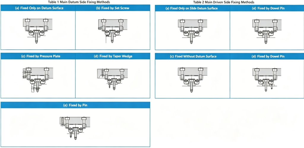
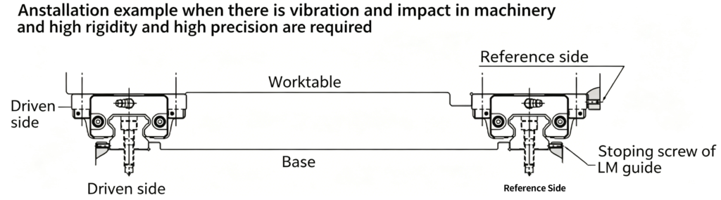
Besides the mounting method using set screws, there are also clamping plate fixing, wedge block fixing, and fixing with pins and taper screws.
Mounting Surface Design
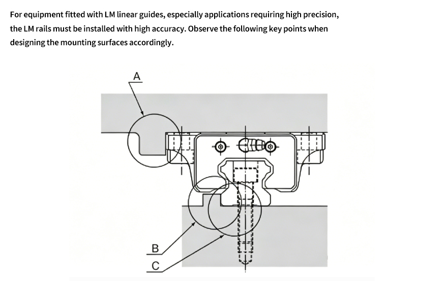
The following shows the recommended dimensions of each mounting surface for standard linear guides.
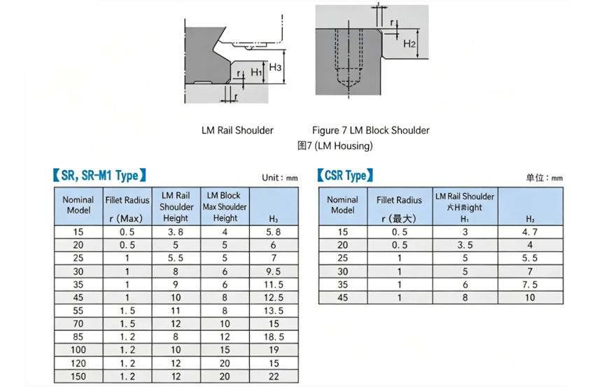
Relevant parameters for partial model numbers and horizontal mounting configurations are recommended here, along with design parameters for linear guides of other brands.
6.Linear Guide Assembly Process & Procedures
1. Mounting Surface Inspection
Remove all burrs, impact marks and contaminants on the machine mounting surfaces before installation. LM linear guides are pre-coated with anti-rust oil.
Wipe off the anti-rust oil thoroughly with cleaning solvent prior to mounting. The reference surfaces are prone to rust once the anti-rust coating is removed; it is recommended to apply low-viscosity spindle lubricating oil.
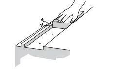
2. Align the reference surface with the LM rail
Place the LM rail gently onto the base, then fasten the assembly bolts loosely to lightly attach the LM rail to the mounting surface. (Align the lateral reference surface of the base with the marked side of the LM rail.)
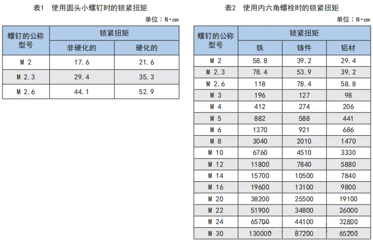
Use clean assembly bolts to secure the LM linear guide. Before inserting bolts into the mounting holes of the LM rail, verify matching hole dimensions in advance. Forcing bolts into misaligned holes will degrade accuracy. Select bolts of appropriate strength grade and material according to the recommended torque values for the rail mounting material (Table 2).
Tighten the set screws of the LM rail in sequence to press the rail firmly against the lateral mounting surface.
If there is no set screw structure, use a bench vise to bring the LM rail into tight contact with the lateral reference surface, then fully tighten the assembly bolts. Afterwards, fasten all fixing bolts one by one in order.
Tighten the assembly bolts to the specified torque using a torque wrench. For the tightening sequence of LM rail assembly bolts: start from the center and work toward both rail ends in order, which ensures stable precision.
Install the remaining LM rails using the same procedure until all installation work is finished.
When no positioning shoulders are available or high precision is required, a marble straightedge or collimator is commonly used. Adjust section by section following the spacing of bolt holes, with repeated tightening and fine-tuning until the dial indicator readings along the full rail or collimator measurement are within 2 μm or better. Long linear guides usually suffer minor deformation. During assembly, slight adjustments are made with a bench vise or rubber mallet (without damaging the rail) to ensure the straightness meets specifications.
3.Slave Side Rail Installation
When installing the slave-side LM rail parallel to the properly mounted reference-side LM rail, the following method is recommended.
Standard Straightedge Method
Place a standard straightedge between the two rails, and use a dial gauge to adjust it parallel to the lateral reference surface of the reference-side LM rail.
Then take the standard straightedge as the reference, adjust the straightness of the slave-side LM rail with the dial gauge, and fasten the assembly bolts sequentially starting from the rail ends.
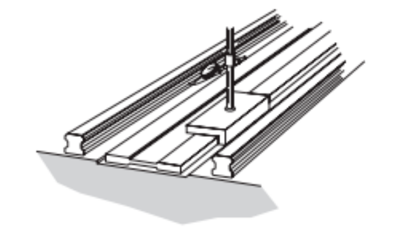
Method of Copying the Reference-Side LM Rail
Method of Copying the Reference-Side LM Rail Mount the worktable onto the LM blocks of the properly installed reference-side LM rail and the loosely fastened slave-side LM rail. Fully tighten the bolts for the two LM blocks on the reference side and one of the two LM blocks on the slave side. Leave the remaining slave-side LM block loosely fastened. Move the worktable, check the rolling resistance during movement, and fully tighten all assembly bolts of the slave-side LM rail in sequence.
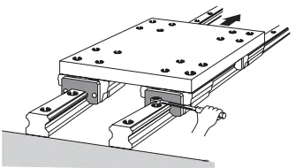
Special Tool Method (Dial Indicator Type)
Use the special tool shown in Figure 17. Starting from one end and proceeding sequentially at intervals of each mounting hole, adjust the parallelism of the reference surface on the slave side against the lateral reference surface of the reference side, and fully tighten the assembly bolts at the same time.
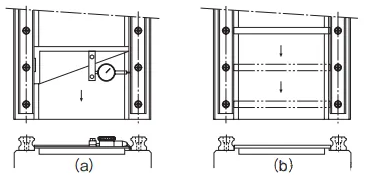
After the master and slave linear guides are installed, drive the hole plugs into the assembly bolt holes until they are flush with the top surface of the LM rail.
4.Worktable Installation
Place the worktable gently on the LM blocks and loosely fasten the mounting bolts.
Use set screws to bring the reference side of the LM blocks into contact with the side reference surface of the worktable for positioning the worktable.
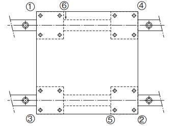
Fully tighten the assembly bolts on both the reference side and slave side to complete installation. Note: The tightening sequence of assembly bolts is shown in Figure 11. Tightening in diagonal order ensures even securing of the worktable.
This method saves time on adjusting the straightness of LM rails and eliminates the need for machined positioning pins for fixation, greatly reducing installation man-hours.
6.Installation Precision Measurement Methods
Straightness Inspection Methods for Single Rail (2 common types for different precision requirements):
① Collimator Inspection Method: Fix the collimator at one end of the rail and adjust its laser beam to run parallel to the rail reference surface. Move the collimator receiver along the full length of the rail and record deviation readings. The maximum deviation value represents the rail straightness error. This method is suitable for high-precision inspection requirements.
② Dial Gauge & Marble Square Ruler Inspection Method: Secure the marble square ruler beside the rail mounting reference surface to align its side face parallel with the rail reference surface. Mount the dial gauge on a stand with its probe touching the rail side. Slide the stand slowly along the entire rail and log gauge reading variations. The total fluctuation range of readings equals the straightness error. This easy-to-operate method applies to standard precision inspection.
Parallelism Inspection Methods for Double Rails (3 practical methods for different installation scenarios):
① Standard Straightedge Method: Place a standard straightedge between the two rails and attach it closely to the lateral reference surface of the reference-side rail. Use a dial gauge to measure the clearance between the straightedge and the lateral reference surface of the slave-side rail at multiple points over the full rail length. The maximum clearance value is the parallelism error of the double rails.
② Reference Copy Method: Mount the worktable on the slides of both the reference-side and slave-side rails. Fully tighten the connecting bolts between the reference-side slides and the worktable while leaving the slave-side slides loosely fastened. Push the worktable to travel along the full length of the rails, and use a dial gauge to measure the height difference on both sides of the worktable. The fluctuation of height difference represents the parallelism error. Adjust the slave-side rail during measurement until the error meets specifications. (This is the most commonly used method.)
③ Special Tool Method: Adopt a dedicated parallelism inspection tool from THK. Take the lateral reference surface of the reference-side rail as the benchmark, inspect the parallelism of the slave-side rail sequentially at intervals of each rail mounting hole, and adjust the position of the slave-side rail simultaneously. Retest after tightening all bolts to guarantee the parallelism meets requirements.
7.Guide Rail Selection Summary
Determine the guide rail type: Ball guide rails are preferred, and the ball retainer type is suitable for most conventional working conditions. The full ball type can be selected for scenarios with limited budget and low precision requirements. Roller guide rails, preferably the roller retainer type, are adopted for high-speed, high-precision and heavy-load working conditions.
Match the corresponding model: SSR/SRS models are prioritized for scenarios with horizontal and radial loads. SHS models are selected for scenarios requiring high force balance such as wall-mounted and vertical installation.
Calculate core parameters: Clarify the force conditions of the guide rail, and calculate the equivalent load, static safety factor and rated service life according to actual working conditions. Select precision/ultra-precision grade rails and corresponding preload grades based on micron-level precision requirements.
Adapt to service environment: Select matching materials, lubrication and dustproof solutions according to application scenarios. Special dedicated accessories are adopted for extreme environments such as dust-free, vacuum, high and low temperature conditions, while economical supporting solutions are applicable to conventional working conditions.
Control installation and inspection: Complete cleaning and lubrication before installation, and mount the reference rail, slave rail and slides in accordance with specifications. After installation, inspect the straightness of single rails and the parallelism of double rails to ensure compliance with precision standards.



Add comment