

Pneumatic & Electrical Components: The Nerves and Vessels of Non-standard Automation
Nerves & Blood Vessels of Non-standard Automation: A Beginner’s Guide to Pneumatic & Electrical Components
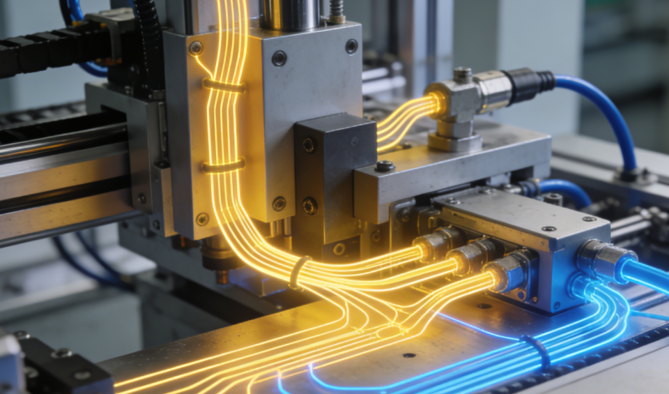
When learning about non-standard automation pneumatic and electrical components, you can clearly split the whole equipment into mechanical skeleton, electrical nerve network and pneumatic blood vessel system. Within the framework of non-standard automation equipment, if mechanical structures serve as the “skeleton”, the electrical system acts as the “nerves” that transmit signals and command movements, while the pneumatic system functions as the “blood vessels” delivering fast linear power. The article sorts out complete components, collaborative pick-and-place workflow and daily maintenance tips, which is friendly for new automation engineers.
1. Electrical System – The “Nerve” Network
The electrical system handles control logic, signal acquisition and power driving.
Core Components:
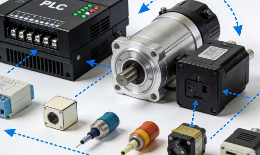
1. PLC (Programmable Logic Controller): The brain of the equipment. It receives input signals, executes pre-set programs and outputs control commands.
2. Sensors (photoelectric, proximity, vision sensors, etc.): The “sensory organs” of the machine. They detect object position, color, dimension and other parameters, and convert physical signals into electrical signals.
3. Servo/Stepper Motors & Drivers: Precise “motion performers” that realize accurate control of position, speed and torque.
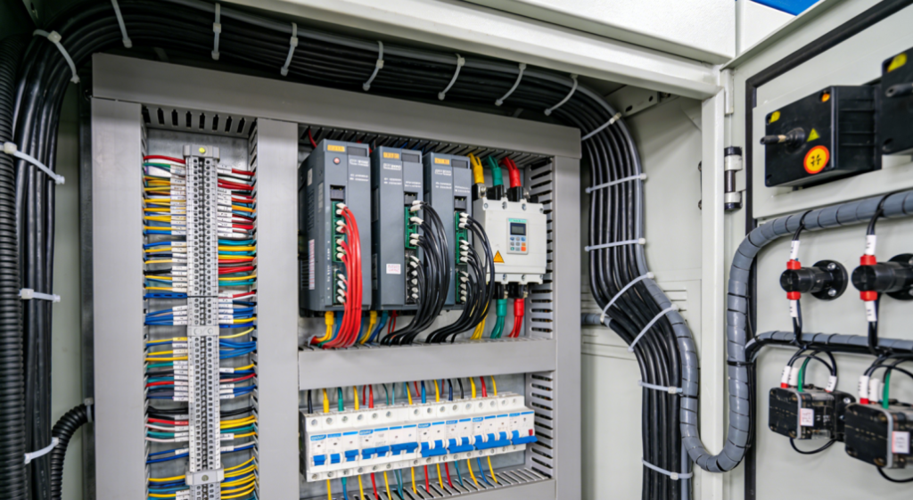
4. Relays & Contactors: Switches for high-power circuits. They use small current to switch on/off high-current loads such as motors and heating tubes.
5.HMI (Human-Machine Interface): The interaction window between operators and equipment, used for parameter setting, status monitoring and operation control.
2. Pneumatic System – The “Blood Vessel” Network
The pneumatic system uses compressed air as the medium to realize fast and simple linear or swinging motions.
Core Components:
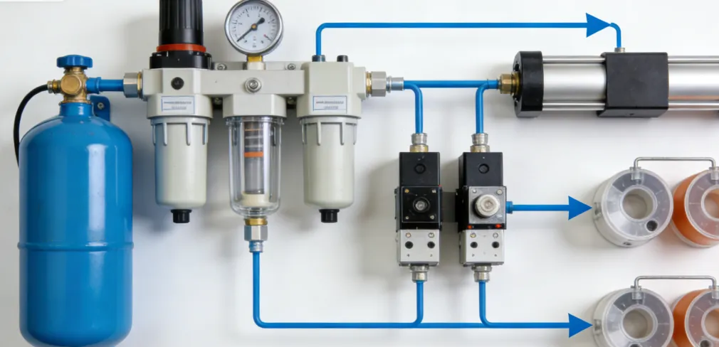
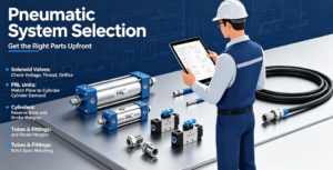
1.Air preparation units (three-point combination): Consisting of filter (removes moisture and oil), pressure reducing valve (regulates air pressure) and lubricator (provides lubrication). They act as the “health caretaker” ensuring stable operation of the pneumatic system.
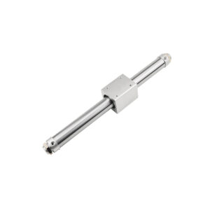
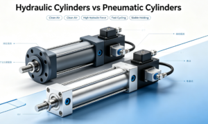
2.Air cylinders: Actuators that convert air pressure energy into linear reciprocating motion, the core parts serving as the extending “arms” of equipment.
3.Solenoid valves: The “switches” of air circuits. Controlled by electrical signals, they adjust the flow direction of compressed air to extend and retract air cylinders.
4.Vacuum generators & suction cups: Generate negative pressure based on the Venturi principle to grip thin and lightweight workpieces.
5.Auxiliary components: Air tubes, fittings, flow control valves (for cylinder speed regulation), mufflers and other accessories.
3. Collaborative Working Process
A typical pick-and-place operation perfectly demonstrates the coordination between the “nerves” and “blood vessels”.
1. Sensing (Electrical System – Nerves): The photoelectric sensor detects the workpiece in position and sends signals to the PLC.
2. Decision-making (Electrical System – Nerves): The PLC program judges that the conditions are met and sends commands to the solenoid valves and servo drives.
3. Execution (Pneumatic & Electrical Systems – Blood Vessels and Nerve Terminals):
The solenoid valve energizes and switches direction. Compressed air drives the air cylinder to extend.
The vacuum suction cup at the cylinder end grips the workpiece.
Meanwhile, the servo motor drives the module to move the workpiece to the target position.
4. Feedback (Electrical System – Nerves): The position sensor confirms the workpiece is placed in place, the PLC controls the solenoid valve to reset, the air cylinder retracts, and the cycle is completed.
Key Points for Basic Understanding
1. Electrical systems focus on signals and logic, while pneumatic systems prioritize power and speed.
2. Electrical control logic and pneumatic circuit diagrams shall be planned first during design.
3. Safety interlocks are critical. Signals from emergency stops and safety light curtains must cut off all power sources (electricity and compressed air).
4. Maintenance tips: Keep electrical components dust-proof and anti-interference; for pneumatic parts, implement waterproof protection, drain moisture regularly and maintain clean air supply.
Further reading for automation engineers:
Control System Guide If you want to learn complete PLC and pneumatic control cases for pick-and-place machines, check the step-by-step tutorials on Control System Guide.
RealPars (A leading global free educational platform for automation)non-standard automation pneumatic and electrical components

Add comment