

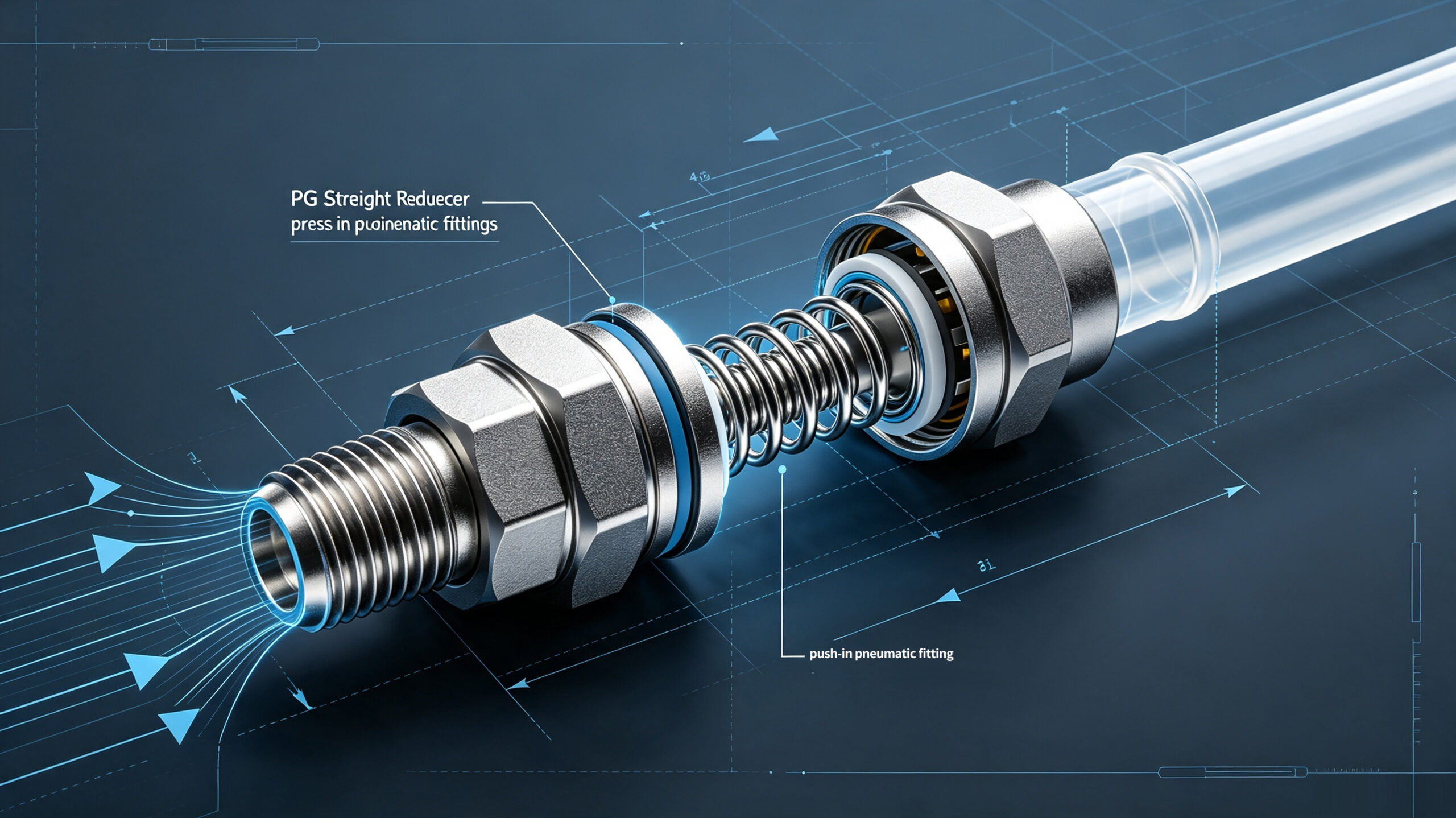
PG Straight Reducer Push-in Fittings, Pneumatic Pipe Connector
Table of Contents
- I.Core Working Principle: Push-Lock Self-Locking, Sealed Flow Passage
- II. Model Selection Guide: Make Proper Choices and Avoid Common Pitfalls
- III. Core Structural Features: Industrial-Grade Durable Design
- IV. Material & Craftsmanship: Wear and Corrosion Resistance for Industrial Working Conditions
- V. Standard Installation Procedures: Fast Assembly Without Errors
- VI. Daily Maintenance & Troubleshooting: Cut Operating Costs
- VII. Wide Range of Application Scenarios
- Conclusion
PG straight reducer push-in pneumatic fittings In pneumatic automation piping systems, reducing pipe connection, quick assembly & disassembly, leakproof sealing are frequent core requirements. As mainstream industrial push-in connectors, PG push-in straight reducer fittings feature a push-lock self-locking structure, tool-free installation and straight reducing flow path. They perfectly solve the connection challenge for air tubing of different diameters. Widely applicable to compressed air and vacuum pneumatic systems, they serve as essential components for pneumatic wiring of automated equipment, machine tools and production lines.
This article fully elaborates core knowledge of PG push-in fittings, covering working principles, model selection, structural features, material technology, installation specifications, maintenance, troubleshooting and application scenarios. With systematic and comprehensive content, it serves as a practical reference to support engineers in precise selection and standardized on-site operation.
I.Core Working Principle: Push-Lock Self-Locking, Sealed Flow Passage
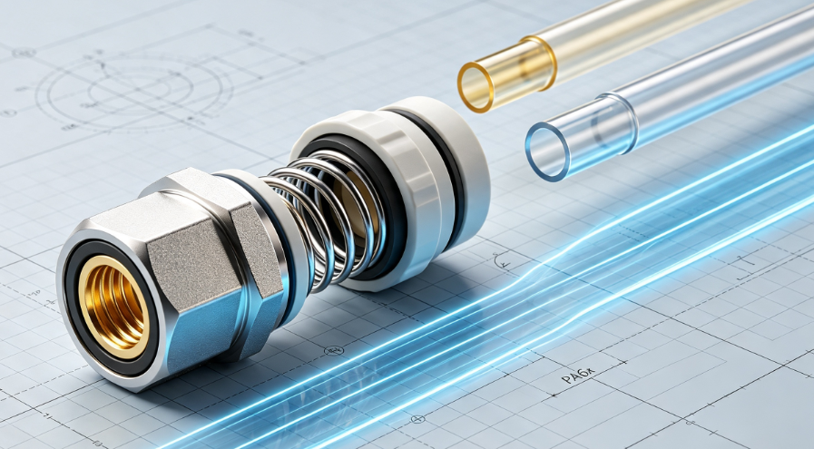
PG Pneumatic Push-Lock Reducer Fittings adopt a dual-core structure of push-in self-locking and elastic sealing. No adhesive, tools or threaded fastening are required. It enables rapid connection with “lock upon insertion and release by pressing”. Suitable for pneumatic positive pressure and vacuum working conditions, it delivers consistent and stable operation.
1.Locking Principle:
Locking Principle: The fitting houses a high-precision stainless steel elastic retaining spring internally. When you insert the air tubing vertically into the fitting port, the tubing wall pushes the spring open. Once you seat the tubing all the way in, the spring rebounds and contracts under its own elasticity. It clamps firmly onto the tubing’s outer wall and builds a mechanical self-locking structure. Beyond basic mechanical clamping, the design brings a valuable pressure self-reinforcing effect. When air pressurizes the pipeline, air pressure pulls the tubing outward. This action strengthens the spring’s clamping force, effectively stopping tubing disconnection and loosening while delivering excellent stability under pressure.
2.Sealing Principle:
The fitting incorporates a built-in high-density NBR elastic sealing ring. After operators insert the tubing fully, the sealing ring closely adheres to the outer surface of the tubing and the inner wall of the fitting. It forms an all-enclosed annular sealing layer and blocks all gas leakage paths. Meanwhile, the integrated straight flow channel inside the fitting eliminates dead zones, delivers smooth airflow and avoids pressure drop loss.
3.Unlocking Principle:
For disassembly, simply press the release cap at the fitting port vertically. This pushes open the internal retaining spring and releases the clamping lock on the air tubing. You can then pull out the tubing directly. The operation is convenient and causes no damage to fittings or tubing, enabling repeated assembly and reuse.
II. Model Selection Guide: Make Proper Choices and Avoid Common Pitfalls
The PG series includes dedicated straight reducer push-in fitting variants. Boasting simple and easy-to-understand model coding standards, this series primarily indicates the outer diameter of matching pipes on both ends. Compatible with industry-standard PU and nylon tubing, it supports mainstream pipe sizes from 4 mm to 16 mm and meets the reduction connection demands of diverse pneumatic pipelines.
1.Model Coding Rules
PG + Large-end Tubing Size – Small-end Tubing SizeCode Definition: PG (Push-In Straight Reducer Fitting) + Outer Diameter of Large Tubing (mm) + Outer Diameter of Small Tubing (mm)
2.List of Standard Regular Models
The mainstream basic models include PG4-3, PG6-4, PG8-4, PG8-6, PG10-6, PG10-8, PG12-8, PG12-10 and PG16-12.
3.Core Parameters for Selection
Operating Pressure: It normally works within 0–1.32 MPa and fits most pneumatic positive pressure systems. It handles vacuum conditions down to -0.1 MPa and suits vacuum suction and negative pressure handling equipment.
Compatible Tubing: Standard PU tubing, nylon tubing and PE pneumatic hoses (general industrial flexible air tubing).
Operating Temperature: -20℃ ~ +60℃, covering regular workshop and equipment operating environments.
Key Selection Tips: First match the outer diameter of the two sections of on-site air tubing. One single reducer fitting completes straight reducing connections without extra adapters. Compared with traditional tee splicing and multi-fitting combinations, this solution cuts leakage risks by over 40% and reduces pneumatic piping labor time by 65%.
III. Core Structural Features: Industrial-Grade Durable Design
PG straight reducer push-in pneumatic fittings adopt a multi-layer modular precision structure. Each component delivers clear functions and operates stably in coordination. The design balances sealing performance, fastening strength and reusability. Its compact and lightweight overall structure suits high-density piping layout on automated equipment.
1.Complete Structural Composition
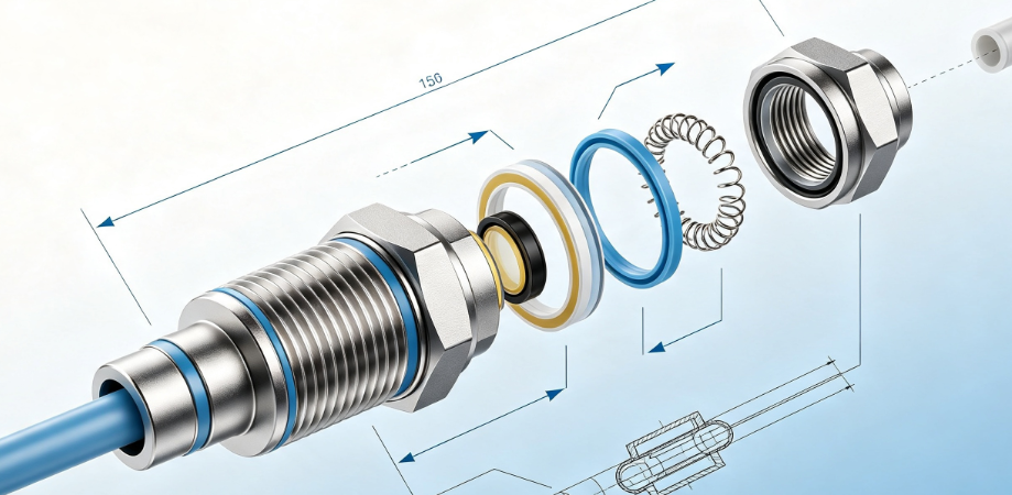
You can see the components from outside inward in sequence: protective release cap, high-strength engineering plastic housing, stainless steel locking retaining spring, fixing ring base, wear-resistant sealing ring and integrated straight inner core. The structure contains no redundant parts and leaves zero loose clearances.
2.Core Structural Advantages
✅ Integrated Straight Reducer Design: Different sizes for two ends enable direct connection between large and small tubing with just one fitting. This simplifies pipeline layouts, cuts sealing points and lowers risks of air leakage.
✅ Anti-Disengagement Self-Locking Structure: The stainless steel retaining spring maintains lasting elasticity and even clamping force. It withstands repeated insertion and removal. Higher pressure boosts its clamping effect to eliminate hidden risks of tubing slippage and air leakage.
✅ Dual Sealing Protection: The thickened built-in NBR sealing ring fits closely against contact surfaces. It blocks dust ingress and prevents leakage under positive pressure and vacuum. Its air tightness meets the ISO 14511 industrial standard.
✅ Compact & Lightweight Build: Its small footprint saves installation space. It fits confined internal equipment areas and dense pipeline arrangements, and supports compact design requirements for automated machinery.
✅ Reusable for Multiple Disassembly & Assembly: The push-lock unlocking structure suffers no functional wear under normal working conditions. Users can insert and pull out tubing repeatedly. Maintenance and replacement require no tubing cutting and reduce overall operating costs.
IV. Material & Craftsmanship: Wear and Corrosion Resistance for Industrial Working Conditions
PG push-in reducer fittings adopt industrial-grade composite materials and precision machining processes. The design balances hardness, toughness, corrosion resistance and sealing performance. It handles complex workshop environments with humidity, dust and common oil contamination and extends overall service life.
1.Materials of Core ComponentsHousing:
High-strength modified PA66 engineering plastic delivers reliable impact resistance and anti-aging performance. The material keeps dimensional stability while offering excellent insulation, making it ideal for auxiliary electric and pneumatic equipment.
Made of 304 stainless steel, the retaining spring maintains consistent elasticity. Anti-rust and anti-corrosive, it handles repeated cyclic operations and remains dependable after numerous plug-in and pull-out cycles.
Sealing components adopt NBR nitrile rubber. Thanks to good oil and gas resistance as well as wear resistance, the material achieves superior air tightness, suitable for compressed air applications within a broad temperature scope.
For upgraded selection: inner core with nickel-plated brass. This option enhances anti-corrosion and anti-fouling capability, perfectly applicable to high-humidity scenarios containing mild corrosive substances.
2. Highlights of Processing Technology
The production uses integrated injection molding. This process leaves no assembly gaps on the housing and builds strong structural rigidity. Precision polishing on the inner port walls removes burrs and scratches. It prevents cuts on tubing that trigger air leakage. Precision grooving at critical sealing positions maintains tight contact for sealing rings. Manufacturers apply passivation and anti-rust treatment to metal parts. These treatments stop rust and jamming during long-term operation.
V. Standard Installation Procedures: Fast Assembly Without Errors
PG push-in reducer fittings support tool-free quick installation. The workflow stays simple and easy to follow. Operators who follow specifications fully can prevent air leakage and tubing disconnection in later operation. You can check the detailed steps below:
1.Tubing Preprocessing:
Select intact standard pneumatic tubing without damage or aging. Use a dedicated tubing cutter to cut the tubing vertically. Keep clean, burr-free and square cuts. Stop debris and burrs from entering the fitting and impairing sealing performance.
2.Pipeline Cleaning:
Clear dust and contaminants from tubing cut ends and fitting ports. Keep contact areas clean and dry with no oil stains or solid particles.
3.Insertion and Locking:
Align the large and small tubing vertically with the corresponding reducer ports. Push the tubing steadily until each tube reaches the fitting base. Avoid loose or suspended tubing. The retaining spring delivers automatic self-locking.
4.Air Tightness Inspection:
Pull the tubing gently after installation and confirm no disconnection. Feed compressed air and check the pipeline for leaks and abnormal vibration. The installation passes inspection if you find no such issues.
5.Disassembly Guidelines:
Press the release cap on the fitting port to fully open the retaining spring. Keep pressing the cap and pull the tubing straight out. Never yank the tubing forcefully. Rough pulling damages the retaining spring and sealing ring.
VI. Daily Maintenance & Troubleshooting: Cut Operating Costs
1.Standard Daily Maintenance PracticesRegular Inspection:
Check fitting connections every week for looseness, air leaks and condensation. Focus on piping joints under vibration and high-temperature operating conditions.
Cleaning & Maintenance: Clear dust and oil stains on fitting surfaces and ports every month. Prevent accumulated contaminants from jamming the retaining spring and breaking sealing performance.
Consumable Replacement: Sealing rings and retaining springs are wearing parts.
Inspect and replace them every 6–12 months for high-frequency applications. Swap aged components promptly to avoid air leakage.
Environmental Protection: Avoid prolonged exposure to direct sunlight and immersion in strong acids or alkalis. Keep fittings away from sharp impacts to prevent housing cracks and tubing damage.
2.Common Faults & Quick Solutions
Fault 1: Air leakage at fitting connection
Causes: Tubing fails to fully seat, uneven cut with burrs, worn or damaged sealing ring, contaminants blocking ports
Solutions: Reinsert tubing firmly until it reaches the base. Recut tubing for a flat end. Clear contaminants inside ports and replace aged sealing rings.
Fault 2: Tubing slips off and cannot lock securely
Causes: Fatigued and deformed stainless steel retaining spring with lost elasticity; non-standard tubing or excessive outer diameter tolerance
Solutions: Replace the retaining spring or the whole fitting. Use tubing of standard dimensions and avoid mixing non-standard tubing.
Fault 3: Stiff assembly & disassembly; release cap fails to rebound after pressing
Causes: Built-up dust and oil inside, rusted retaining spring, minor deformation of internal components
Solutions: Disassemble and clear internal contaminants. Apply a small amount of grease for light rust. Replace any deformed components directly.
Fault 4: Leakage and unstable pressure retention under vacuum conditions
Causes: Poor sealing contact, slight looseness in piping connections
Solutions: Reinsert and lock the tubing securely. Check sealing parts for integrity and use dedicated vacuum sealing components.
VII. Wide Range of Application Scenarios
PG push-in straight reducer fittings fit all kinds of pneumatic reducing piping applications. Thanks to stable performance, low leakage and easy maintenance, these fittings serve as universal components for industrial automation. Below are its core application sectors:
- Automated Equipment: Robots, production line machinery and servo pneumatic control systems. One fitting connects air tubing of different sizes for pneumatic actuators.
- Machine Tools: CNC lathes and machining centers use these fittings on auxiliary pneumatic pipelines. They complete reducing connections between main air supply lines and smaller branch tubes.
- Vacuum Systems: Vacuum suction platforms, negative-pressure handling gear and vacuum packaging equipment. The fittings support reducing piping connections under vacuum pressure holding conditions.
- Air Supply Delivery Systems: Workshop main air pipelines, pneumatic tool stations and post-compressor piping renovation. They simplify overall piping layouts.
- Light Industry & Packaging Machinery: Pneumatic pipelines on printing, packaging and textile equipment. The compact design meets piping demands in dense and confined spaces.
- Custom Automation Equipment: Modification and upgrade of all custom pneumatic machinery. These fittings flexibly handle connection tasks for tubing sections with different outer diameters.
Conclusion
PG straight reducer push-in pneumatic fittings adopt a push-lock self-locking structure together with integrated reducer design. To begin with, they enable tool-free quick assembly and disassembly alongside low leakage and reliable stability. Thanks to the above merits, the fittings tackle typical industrial issues including mismatched tubing diameters, cumbersome pipeline layouts, air leakage and difficult maintenance. In addition, sophisticated material processing, standard specifications and easy installation help lower total expenses on pneumatic pipeline installation and maintenance. For this reason, these fittings become the ideal choice for lightweight, high-efficiency and standardized pipeline arrangements within industrial pneumatic systems.

Add comment