

Short Shaft Reliability Goes Beyond Dimensions
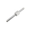
Short Shaft Reliability Goes Beyond Dimensions From visual inspection, the output shaft of this compact actuator is already very short.
By common mechanical intuition, shorter overhang generally delivers higher stiffness. This shaft would not seem to be the first location prone to failure.
However, during actual operation, if these phenomena occur one after another:
1.Sudden increase in vibration near a certain rotational speed;
2.Repeated loosening of the coupling;
3.Abnormal temperature rise at the drive‑end bearing;
4.Gradual drift in positioning accuracy.
On‑site troubleshooting tends to attribute the issues separately to shaft diameter, coupling selection, or ball‑screw alignment.
All these aspects merit investigation. Yet before modifying individual components further, one more fundamental question should first be raised:
For every type of force within this mechanism, who is supposed to bear the load originally, and where does the load path finally close?
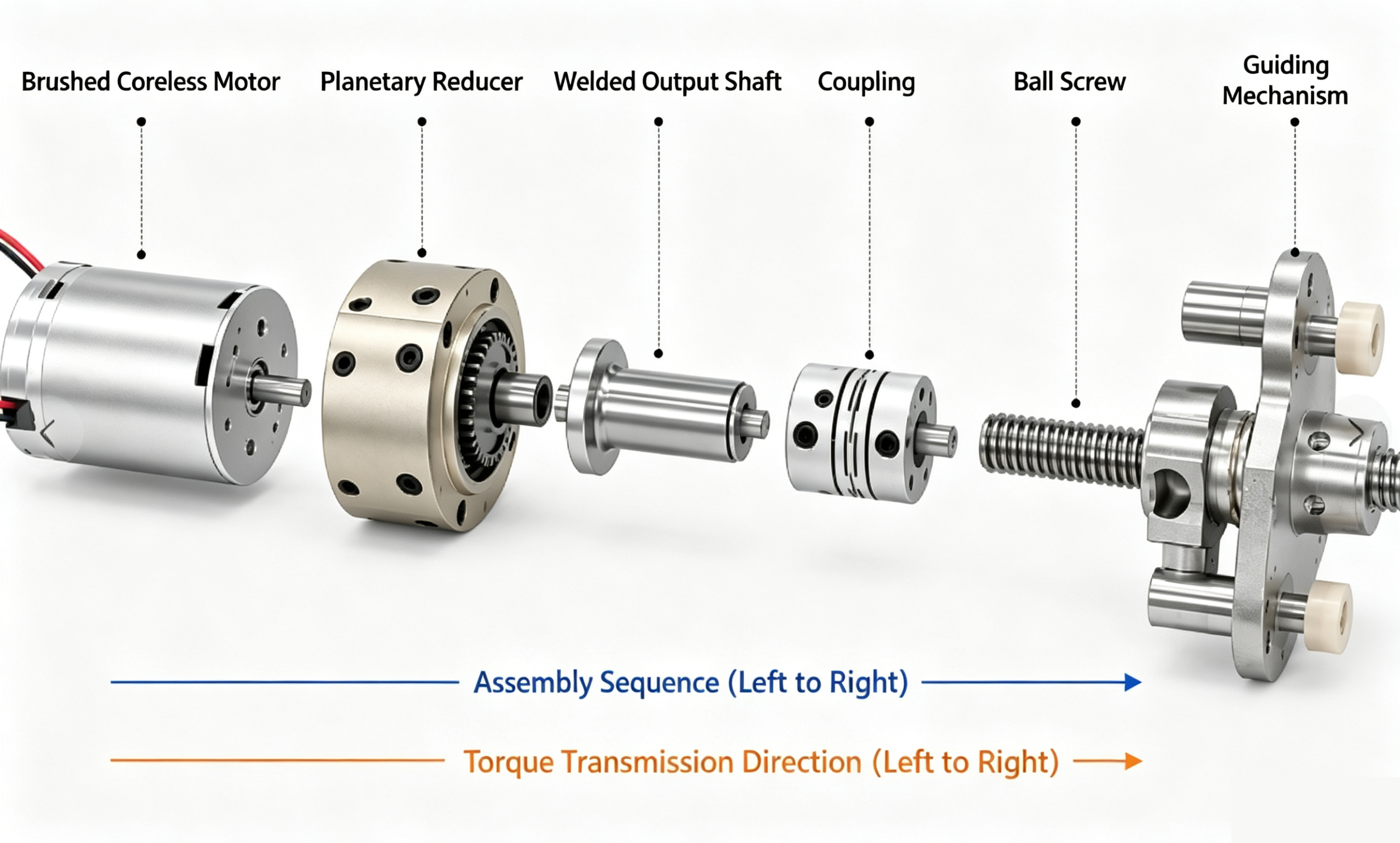
We are now discussing a transmission chain as follows:
Brushed hollow‑cup motor → Planetary gear reducer → Combined short output shaft → Coupling → Ball screw → Guide mechanism
Herein, the shaft segment at the reducer output and the welded output shaft together form the combined short output‑shaft assembly mentioned above.
Dimensionally speaking, it is already very short. However, a “short shaft” only describes the geometry of the part; it does not directly imply that the actual loads it carries are simple.
What truly needs to be confirmed is:
Where the effective support is located, where external loads are introduced, and whether these loads close along the intended load‑path.
If the load‑path is not properly managed, a shaft that appears short and robust can still become one of the earlier locations in the system to exhibit problems.
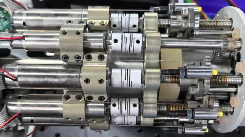
Figure 1|The more compact the structure, the more prone mutual coupling becomes among support, alignment, connection and guidance. Even with closely spaced components, force relationships can still be complex.
1.Motion can be transmitted, yet forces may not follow the correct path
From a kinematic perspective, this path is clear:
Motor output torque → Torque amplified by reducer → Transmitted through short output shaft → Coupling joint → Ball screw converts rotary motion into linear motion
The guiding mechanism restricts the direction of motion. This forms a kinematic chain. A closed kinematic chain only guarantees motion transfer. To judge whether a mechanical system is reliable, we further examine how loads propagate and where loads are supported. This is the load chain.
When load distribution is reasonable, several relationships should generally be satisfied:
1.Torque is transmitted along the path of motor‑reducer‑short output shaft‑coupling‑ball screw.
2.The axial force generated by the ball screw shall be borne by the fixed end or a dedicated axial support to prevent further transmission toward the drive end.
3.Lateral forces and overturning moments acting on the worktable are mainly carried by the guiding mechanism.
4.The coupling transmits torque and compensates for mounting errors within a specified range.
5.The short output shaft must not serve as an unintended fallback path for external transverse loads without prior design load allocation.
The review sequence should follow this logic: first identify which component ultimately sustains each type of load, then calculate component strength. If the load closure path remains unclear, merely optimizing the shaft diameter, material or coupling model is likely nothing more than a partial patchwork.
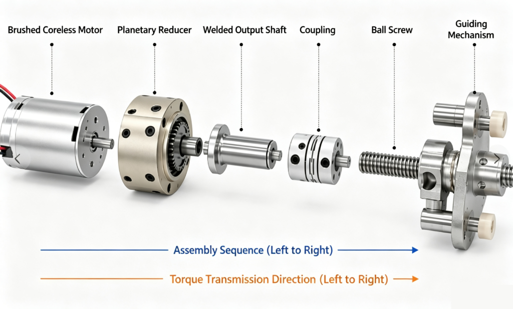
Figure 2|After disassembling the assembly, the relationships among torque transmission, axial support and lateral restraint become easier to observe.
2. A Short Shaft Does Not Necessarily Mean a Short Effective Cantilever
When you assess bending risks on the short output shaft, first find the positions that deliver real support, and then pinpoint where external forces act. For preliminary evaluation, you may simplify contact forces between physical bearings and the housing into a “support boundary”, or an equivalent support boundary. The span from this support location to the actual point where external forces act defines the effective cantilever we examine throughout this analysis.
This simplified position serves only as an analytical concept and cannot replace the actual support topology. The formal design must still consider practical factors such as bearing span, housing stiffness, fits and preload. In this structure, the overall short output shaft does not appear long; nevertheless, the distance from the internal effective support to the loading point of the downstream stage is what ultimately determines its bending response.
When the cross‑section, material and load type remain approximately unchanged, two trend relationships can be used for preliminary evaluation:
M_b ≈ F_r L
δ ∝ F_r L³
Where:
1.Fr = Additional radial load acting on the output shaft system;
2.L = Distance from the effective support to the load application point, i.e., the effective cantilever length;
3.Mb = Bending moment near the support;
4.δ = Shaft‑end deflection.
We use these two relationships only for trend judgment, and they cannot substitute for formal strength calculations. When we evaluate bending moment and deflection, the distance from the external load to the effective support often matters more than the shaft’s apparent physical length. Under the simplified conditions above, effective cantilever length strongly influences deflection.
For short‑shaft design, the dimension that truly needs shortening is usually the effective cantilever, not the visually observable shaft segment.
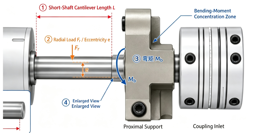
Figure 3 Schematic of Loads Acting on the Short Output Shaft
Figure 3|When assessing risks of the short shaft, first locate the effective support and the external load application point, then determine the effective cantilever between them. L, Fr and Mb in the diagram illustrate the load‑force relationship.
3.The Shaft Is Designed to Transmit Only Torque — Where Do Additional Forces Originate?
If the short output shaft is designed to transmit only torque, the analysis is relatively straightforward. Additional loads may originate from several sources:
1.The ball‑screw supports fail to absorb axial or transverse loads locally.
2.Insufficient stiffness of the guiding mechanism causes lateral forces to feed back to the ball‑screw side.
3.Assembly errors lead the connecting components to exert continuous additional reaction forces.
These loads may not be the primary design loads originally allocated to the short output shaft. If these forces are not sustained at the locations intended to carry them, they will be redistributed to other components according to the stiffness and constraint relationships of the mechanism. Eventually, the extra loads may become concentrated on a component that appears to be the most robust.
Once the load sources are identified, their points of application must also be examined. Even if the additional radial force itself does not increase, the bending moment and deflection borne by the short output shaft may rise as long as the load acts farther away from the effective support.
In field cases where a short, sturdy short output shaft still experiences vibration, overheating or loosening, we should not jump to the conclusion that “the shaft has insufficient strength”. Instead, we first need to confirm whether the actual radial forces and bending moments it withstands exceed the load limits defined in the original design.
4. Five Checks to Determine Whether the Short Shaft Carries Extra Loads
The preceding analysis can be condensed into a quick reference checklist:
1.Where are the locations providing real support?
Locate the supports that restrict radial displacement and rotation of the short output shaft. Do not rely merely on the outline of the housing or bearing pedestal.
2.Where do external loads apply to this shaft?
Identify where reaction forces from the downstream structure transfer into the short output shaft, then evaluate the distance from this load point to the effective support.
3.Who ultimately takes up the axial force generated by the ball screw?
If the load‑carrying location cannot be defined clearly, axial force may travel along undesired paths toward the drive end.
4.Who bears lateral forces and overturning moments?
First verify whether the guiding mechanism provides the lateral constraints assigned by design. If not, the ball screw, coupling and short output shaft may be forced to carry these loads.
5.Is the shaft transmitting torque only, or is it under both torsion and bending simultaneously?
The latter represents a combined bending‑torsion loading state. Analysis methods, life assessment and support design must be adjusted accordingly.
5. Do Not Rush to Increase Shaft Diameter — First Clarify the Load Paths
After confirming that the short output shaft is subject to additional loads, design improvements can follow this sequence:
1.First, contain each force at its intended load‑taking location. Clarify which components absorb the ball‑screw axial force, table lateral force and overturning moment. Stop loads that ought to be restrained downstream from travelling onward to the drive end.
2.Then relocate external load points as close to the effective support as practicable. Optimize the support arrangement, shorten the span between the load point and support, and reduce the effective cantilever.
3.Apply local reinforcement only at the final stage. Once load paths are well defined, evaluate the local load‑carrying capacity of shaft diameter, fillets, joints and material selection.
Merely enlarging the shaft diameter only boosts local load‑bearing capacity. When load paths remain flawed, the end result may be a sturdier structure that still bears improper loads.
6. Shaft Length Is Only Superficial; the Load Path Is What Really Matters
A short‑built short output shaft does not guarantee reliability. Two factors truly require examination:
First, how far the external load acts from the effective support.
Second, whether the shaft merely transmits torque, or is forced to carry additional radial forces and bending moments.
The former governs the cantilever effect, while the latter determines whether the shaft operates under pure torsion or combined bending‑torsion loading.
Therefore, start with this question: Who is supposed to carry these forces originally, and where do they end up? A short output shaft can be compact and robust. Nevertheless, if the load paths remain poorly arranged, it may still become one of the earliest failure points within the system.



Add comment