

Resolve Pain Points of Automated Vacuum Suction Cups
Table of Contents
- First Important Distinction: Catalog Rated Suction Is Not Safe Handling Load
- Good Readings at the Vacuum Source Do Not Equal the Same Vacuum Level Beneath Suction Cups
- Vacuum Level and Suction Flow Rate Are Two Separate Issues
- Workpieces Stay Secure at Rest, Yet May Face Instant Overload During Rapid Acceleration
- When Handling Workpieces Vertically, Friction Usually Bears the Critical Load
- Four Suction Cups Do Not Always Share Loads Evenly
- Mismatched Suction Cup Shape and Material Ruins Sealing, Even With Larger Diameters
- Vacuum Switches Act Not Just As Displays, But As Part of The Safety Chain
- A Typical On-site Scenario: Workpieces Stay Secure at Low Speed, Yet Slip Consistently at the Same Segment After Speed Increases
- Recommended Troubleshooting Sequence
- Summary
Resolve Pain Points of Automated Vacuum Suction Cups
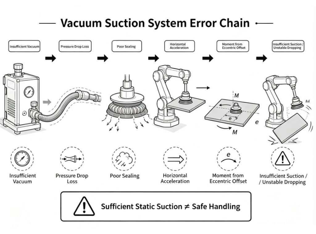
The robotic vacuum gripper worked excellently on the test bench, holding the steel plate steadily for over ten seconds. Once running under automatic cycle mode, the workpiece stayed secure during vertical lifting but began sliding upon horizontal acceleration, and fully detached during emergency stops.
Engineers rechecked calculations: the workpiece load was below 200 N, and the total catalog suction force of four suction cups exceeded 600 N with sufficient surplus. The team then doubted the vacuum generator and suction cup quality and upgraded to larger suction cups.
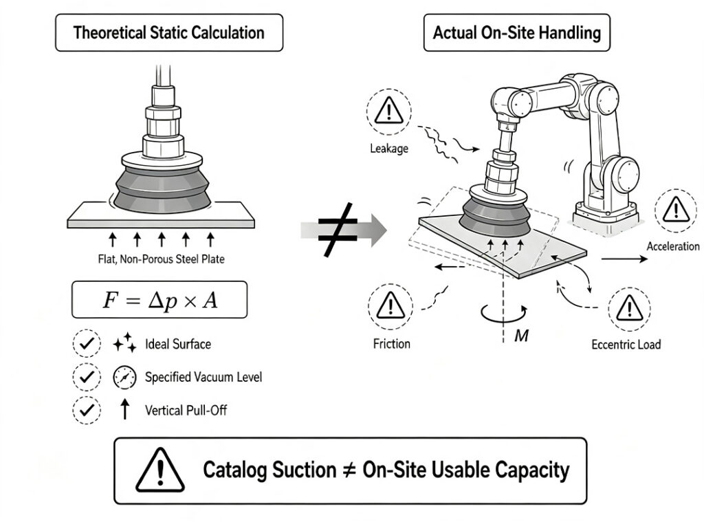
In fact, catalog suction parameters apply only to specified vacuum pressure, ideal surfaces and vertical pulling conditions. On-site conditions involve air leakage, pressure losses, acceleration loads, lateral friction, eccentric torque and sudden vacuum loss. Adequate static calculated suction cannot ensure reliable gripping for the full material handling cycle.
First Important Distinction: Catalog Rated Suction Is Not Safe Handling Load
A suction cup generates its basic holding force from the pressure difference between ambient pressure and the internal pressure inside the cup. Under ideal conditions, we express this relationship with the formula:
F = Δp × A
Δp refers to the pressure differential the vacuum system creates, and A means the effective adsorption area of the suction cup. The formula itself holds true, but it only describes theoretical static force that acts perpendicular to the workpiece surface.
Nearly all catalog data relies on clear preconditions. Schmalz releases public technical documents stating that its suction cup data originates from defined vacuum levels and surface conditions, and excludes any safety factor. Holding capacity drops when workpieces are porous, actual vacuum levels fall short of targets, or loads act in the tangential direction.
For this reason, verifying that four suction cups deliver combined theoretical suction greater than the workpiece weight only marks the first step. Engineers still need to answer these key questions: What vacuum level actually exists at each suction cup? Which directions do loads apply during movement? What scenarios bring the most dangerous acceleration and emergency stops? Do all four suction cups maintain effective contact with the workpiece?
Good Readings at the Vacuum Source Do Not Equal the Same Vacuum Level Beneath Suction Cups
Field technicians often mount vacuum gauges close to vacuum generators. The readings reflect conditions at the vacuum source, yet they do not always match the actual vacuum inside suction cup chambers or at the end of hoses.
Overlong or undersized hoses, flow restriction at fittings, insufficient valve flow capacity and clogged filters all extend evacuation time. When suction cups first contact a workpiece, the system must evacuate air trapped inside pipelines and cup cavities. If the robot waits only for a fixed delay before lifting, the suction may not yet reach the required holding force.
A more reliable practice places vacuum switches or sensor points as close to the load as possible. Program the control logic to trigger lifting only after vacuum hits the threshold value, instead of relying purely on a fixed valve opening duration in milliseconds. Engineers should also log the time from initial contact to threshold vacuum, and monitor whether this interval gradually rises across batches of workpieces.
Vacuum Level and Suction Flow Rate Are Two Separate Issues
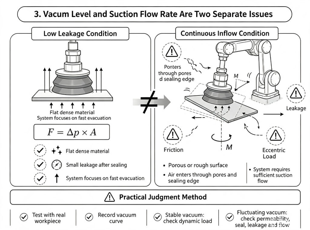
Seals on flat dense metal or glass create minimal leakage, so the system only needs fast air evacuation. Cartons, timber, rough castings and warped boards let air leak constantly through pores and cup rims.
Higher ultimate vacuum does not always solve the problem. Generators need adequate suction flow to compensate for continuous inflow. SMC selection guides list leakage, flow and response time independently, and note leakage suppresses vacuum below required working pressure.
Test with real workpieces and log vacuum curves. Stable vacuum means you prioritize dynamic load checks. Low or fluctuating vacuum requires inspection of material breathability, cup seals, pipe leaks and generator flow.
Workpieces Stay Secure at Rest, Yet May Face Instant Overload During Rapid Acceleration
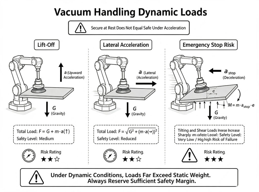
Suction cups mainly counteract gravity while the workpiece hangs stationary. Upward acceleration adds extra inertial forces. Lateral acceleration, path turning and emergency stops create tangential loads and swinging torque.
Schmalz’s calculation examples define required holding force based on the worst operating condition across the full handling cycle. Their formulas incorporate acceleration values, safety factors and friction coefficients. Emergency stops deserve special attention: even if this motion occurs only once per cycle, it often creates greater risks than steady constant-speed travel.
Design teams extract maximum acceleration, deceleration and posture variation data directly from robot or motion axis parameters, instead of relying solely on average cycle speeds. Technicians run separate verification tests for regular movement and safety stop sequences during commissioning. A suction system that succeeds during low-speed teaching cannot always withstand the motion trajectories used in mass production.
Resolve Pain Points of Automated Vacuum Suction Cups
When Handling Workpieces Vertically, Friction Usually Bears the Critical Load
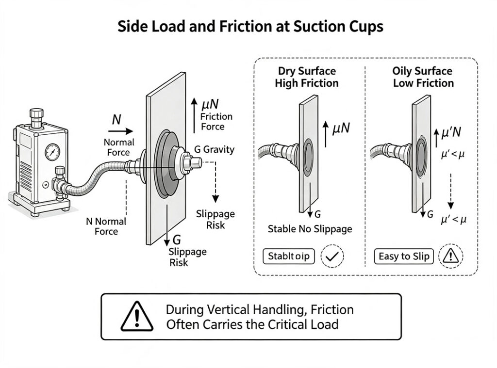
When suction cups lift horizontal plates from above, gravity acts nearly parallel to the suction force. Once operators rotate the workpiece into a vertical position, gravity turns into tangential force along the contact surface. Friction between suction cups and the workpiece becomes the primary barrier against downward slippage.
The available tangential force roughly depends on friction coefficient μ and normal suction force N. Oil films, water, dust, release agents and surface coatings all alter the value of μ. No universal figure from product catalogs can accurately cover all such variations. Schmalz also explicitly recommends testing friction characteristics using actual workpiece surface conditions.
For this reason, identical suction cups operating under the same vacuum level may hold workpieces firmly on dry panels yet allow slow slippage on oil-coated plates. If vertical workpiece handling is unavoidable, run tests based on the worst surface condition and limit unnecessary lateral acceleration and deceleration.
Four Suction Cups Do Not Always Share Loads Evenly
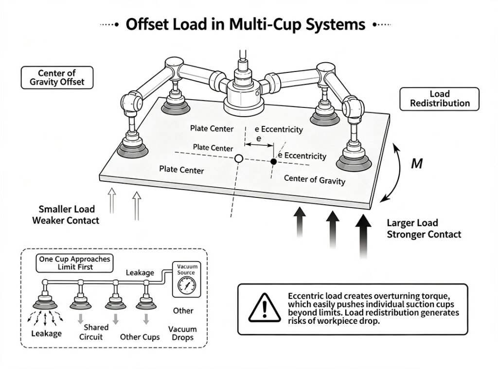
Designers often distribute loads for multi-cup grippers by dividing total load by the number of suction cups. This calculation assumes simultaneous, equal-height, equal-stiffness contact for every cup and perfectly flat workpieces.
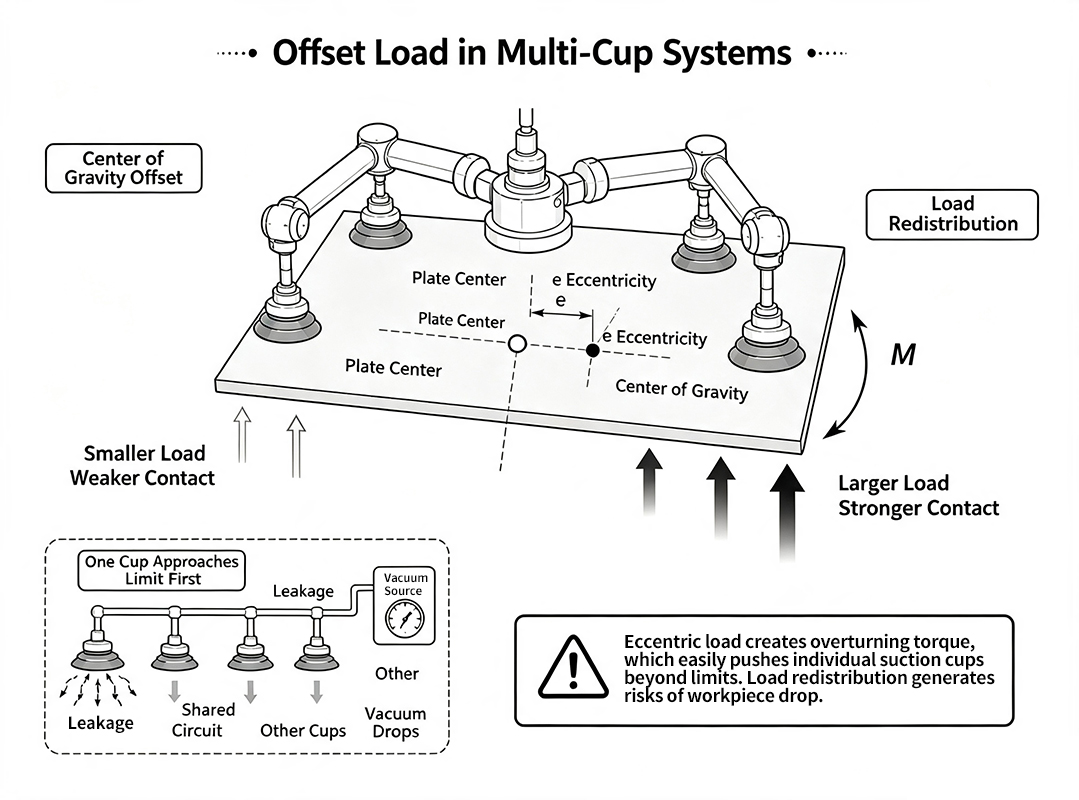
On-site conditions such as warped plates, uneven mounting frames, suction cup height tolerances or insufficient compression on individual cups redistribute loads. When a workpiece’s center of gravity drifts away from the geometric center of the suction array, overturning torque develops and pushes one side of suction cups closer to their load limits. If air seeps into the rim of one suction cup while multiple cups share a single vacuum circuit, falling vacuum pressure impairs performance for all connected cups.
For these reasons, engineers arrange multi-cup layouts around the workpiece center of gravity and allow adequate flexible travel. They add throttling, isolation or vacuum retention on individual branches when necessary. Beyond calculating overall suction capacity, teams must analyze system behavior if any single suction cup fails.
Mismatched Suction Cup Shape and Material Ruins Sealing, Even With Larger Diameters
Flat suction cups work best on flat, rigid surfaces. Bellows suction cups absorb moderate height differences and adapt to curved surfaces, yet designers must also account for their deformation and stability. Hard suction cups struggle to adhere to rough surfaces. Overly soft cups deform and curl at the rim under lateral loads.
Workpieces also present variable conditions. Large suction cups pull thin sheets into local indentations. Packaging films can block suction openings. Grooved surfaces let sealing rims span continuous leakage paths. Larger suction cup diameters raise theoretical adsorption area, yet calculated performance gains never materialize unless the effective sealing area grows accordingly.
Engineers evaluate cup profile, material hardness, allowable curvature, compression travel, operating temperature, oil-water conditions and surface marking requirements during selection. Teams test critical workpieces with actual samples and real production cycle timings. Static trials on a single ideal steel plate cannot deliver reliable conclusions.
Vacuum Switches Act Not Just As Displays, But As Part of The Safety Chain
A dependable system needs to track at least three conditions: whether vacuum fully builds, whether vacuum drops during transport, and how long vacuum persists after a fault occurs.
Operators risk premature lifting if they set the vacuum threshold too low before the workpiece secures firmly. An excessively high threshold forces the system into lengthy waiting cycles. Sensors placed far from suction cups often fail to detect leakage near the cup rim. For heavy or hazardous workpieces, designers evaluate check valves, branch isolation, vacuum storage volume and mechanical anti-drop devices. Teams also define deceleration, shutdown or safe lowering sequences once pressure loss happens.
ISO 4414 outlines reliable operation and hazard control for pneumatic systems under intended working conditions. SMC’s official manuals also warn that worn, cracked suction cups and pipeline leakage pull vacuum levels downward. Engineers should prepare anti-drop protection for heavy or dangerous loads in case gripping force disappears.
A Typical On-site Scenario: Workpieces Stay Secure at Low Speed, Yet Slip Consistently at the Same Segment After Speed Increases
This describes a generic engineering scenario without targeting any specific manufacturer.
A four-suction-cup gripper transports oil-covered thin sheets. Operations run smoothly under manual control and low-speed cycles, yet workpieces keep falling during lateral acceleration once teams raise the cycle speed. On-site staff initially planned to install a larger vacuum generator. After logging vacuum curves measured close to the suction cups, they found steady peak vacuum values and no abrupt leakage spikes before each workpiece drop.
Further inspection revealed key root causes. Gravity relies fully on friction once equipment rotates sheets into vertical orientation. The suction cup layout sits offset from the workpiece center of gravity, so the two outer suction cups receive minimal compression. The team repositioned suction cups and adjusted flexible floating heights. They lowered acceleration values for the highest-risk motion segment, verified friction performance using actual oil-coated panels, and raised the vacuum threshold for lift initiation. These adjustments finally stabilize operation.
This case delivers a clear lesson. Higher air supply flow does not always solve faults when vacuum readings remain normal. The specific motion segment where dropping occurs provides the most critical diagnostic clue.
Recommended Troubleshooting Sequence
- Locate drop phase: picking, lift, flip, lateral movement, emergency stop or sustained hold.
- Log vacuum curves at suction cups: track build time, minimum value and pre-fault changes; ignore only source-side gauges.
- Check leakage & flow: verify real workpieces, cup seals, fittings, hoses, valve bore and generator suction flow.
- Audit contact status: cup material, type, compression, surface oil, roughness, warpage and breathability.
- Recalculate dynamic loading: use worst-case orientation, peak acceleration, emergency stops and proper safety margins.
- Assess multi-cup load sharing: gravity offset, torque, single-cup contact and shared-line cascading failure.
- Test abnormal protection: simulate cup separation, broken piping or air loss to confirm threshold, isolation and anti-drop performance.
Summary
Calculations may yield sufficient suction force, yet workpieces still slip away. Errors rarely originate from flawed formulas. Most formulas only account for ideal static conditions.
Engineers map vacuum level, suction flow, sealing performance, handling orientation, acceleration, friction, center of gravity and fault protection into one complete system chain. This method reveals the actual safety margin. Theoretical suction values serve as a starting benchmark. Real workpieces and actual motion trajectories deliver the final verdict.
Have you encountered this issue on site: suction systems hold firmly at low speed but drop loads after speed increases? Did troubleshooting trace the root cause to leakage, surface oil contamination, eccentric loading, motion parameters or protection logic? Feel free to share your experience in the comments.
Why Do Workpieces Fall Even With Sufficient Calculated Suction Force | Vacuum Gripper Troubleshooting
ISO 4414 Pneumatic fluid power — General safety requirements for systems and components


Add comment