

Detailed Explanation of Ball Screw Selection Procedures and Calculation Methods
Detailed Explanation of Ball Screw Selectionis a systematic engineering process that requires comprehensive consideration of multiple factors including load, speed, precision, service life and more. Below is a clear and complete set of ball screw selection procedures applicable to the most common ball screws.
Core Procedures for Ball Screw Selection
1.Clarify Design Requirements and Operating Condition Parameters
This is the foundation of selection and must be as accurate as possible.
1.Axial Load (F): The maximum thrust the ball screw must withstand, including working load, guide rail friction, inertial force generated by acceleration, etc. Constant-speed load and acceleration load shall generally be calculated separately.
Load during acceleration: Facc=Fload+Ffriction+m⋅a
Fload: Actual working load (N)
Ffriction: Guide rail frictional resistance (N), equal to μ⋅m⋅g for horizontal mounting; tilt angle shall betaken into account for inclined installation
m: Total mass of moving parts (kg)
a: Maximum acceleration (m/s2)
Load at constant speed: Funif=Fload+Ffriction
2.Operating Speed (V): Maximum required linear speed (unit: m/min or mm/s).
3.Stroke Length (L): Effective working stroke of the ball screw (mm).
4.Positioning Accuracy and Repeat Positioning Accuracy: Absolute accuracy and repeatability required by the system (±mm or ±μm). This directly determines the precision grade of the ball screw (C1–C10; smaller numerical value indicates higher precision).
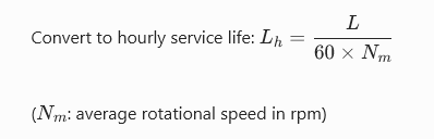
5.Service Life (Lh): Expected design life in hours (e.g., 20,000 hours).
6.Mounting Method: It determines the support configuration of the ball screw and affects critical speed and column stability. Common types are as follows:
- Fixed-Supported (FK): Most widely used with good rigidity.
- Fixed-Fixed (FF): Highest rigidity, applied to scenarios requiring high precision and high stiffness.
- Supported-Supported (KK): Suitable for light loads and long strokes.
- Fixed-Free (FA): Adopted for short strokes and vertical mounting.
7.Operating Environment: Presence of dust, cutting fluid, high temperature and other conditions determines whether dust covers, seals or special materials are required.
2: Preliminary Selection of Ball Screw Parameters
1.Lead (Ph): Selected according to the travel speed and maximum motor speed.
·Formula: Ph=NmaxV×1000(Ph: Lead in mm; V: Speed in m/min; Nmax: Maximum motor speed in rpm)
·Trade-off: A large lead delivers fast feed speed yet lower positioning accuracy and requires higher torque; a small lead offers superior precision and lower torque demand, but limits travel speed.
2.Precision Grade: Select from manufacturer catalogs based on the accuracy requirements determined in Step 1. For example, C5 and C7 grades are widely used in general machine tools, while C3 and C2 grades are adopted for high-precision equipment.
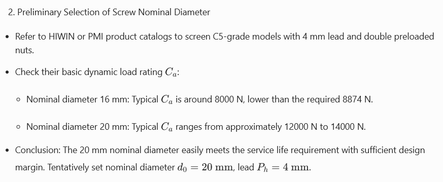
3.Nut Type: Selected according to installation space and whether preload for backlash elimination is required.
- Single Nut: Compact structure with slight backlash.
- Double Nut Preload Type: Eliminates axial backlash to improve rigidity and precision, yet features a longer overall length and slightly higher friction.
3.Preliminary Size Selection Based on Axial Load and Service Life
This is the core calculation section.
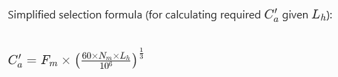
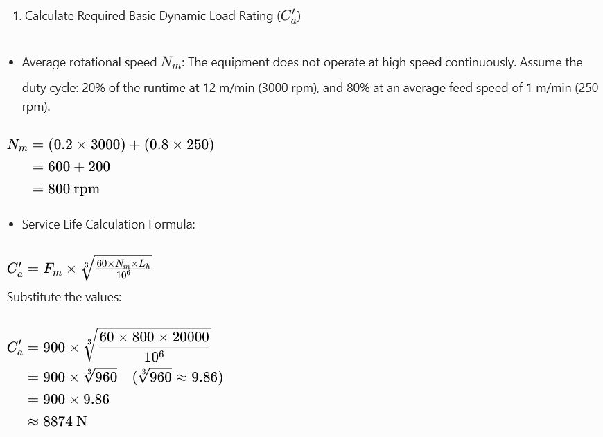
1.Calculate Required Basic Dynamic Load Rating (Ca′):
Calculate the required basic dynamic load rating of the ball screw based on the expected service life Lh (hours) and axial load Fm (mean equivalent load for variable loads) or maximum load.
Basic life formula:


2.Static Load Safety Verification

4.Check Critical Speed and Column Stability
To prevent resonance at high speeds or buckling under compressive load of the ball screw.
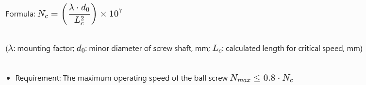
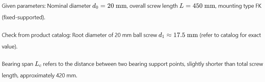
1.Critical Speed (Nc):
Lateral vibration will occur on the ball screw itself, and its limiting rotational speed is affected by mounting method, screw diameter and span (distance between supports).
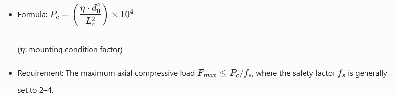
2.Column Stability (Pc):
When the ball screw bears an axial compressive load, longitudinal buckling may occur. The critical compressive load is affected by the mounting method, screw diameter and span length.
5.Calculation of Drive Torque and Motor Power
1.Calculate Drive Torque (T):
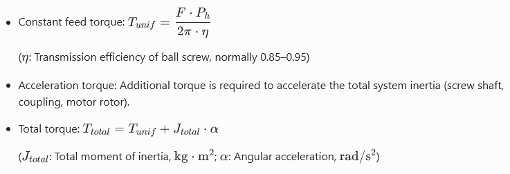
2.Motor Selection:

6: Final Determination and Auxiliary Component Selection
1.Finalize the following parameters based on the above verification results:

2.Selection of Auxiliary Components:
Support Bearings: Select dedicated angular contact bearing assemblies for ball screws capable of bearing axial loads.
Couplings: Choose rigid couplings or diaphragm couplings to minimize backlash.
Lubrication System: Confirm the lubrication method (grease lubrication or oil lubrication) and select corresponding parts.
Dust Protection System: Fit wipers or protective covers.
Selection Flow Chart (Quick Review)
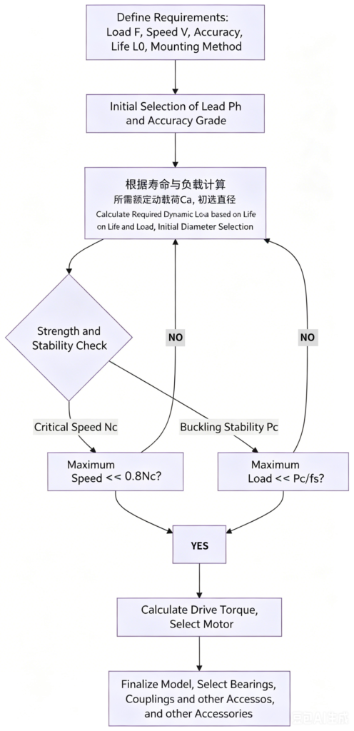
Following the above procedures, you can complete the ball screw selection systematically and comprehensively.
Now we will walk through a detailed practical case to fully demonstrate the ball screw selection workflow. This case covers thorough details to replicate the thought process of real-world engineering selection.
Case Study: Ball Screw Selection for Z-Axis of Vertical CNC Drilling & Milling Platform
1: Define Design Requirements and Operating Condition Parameters
We are designing a compact vertical CNC drilling and milling platform, and need to select a ball screw for the Z-axis that drives the spindle’s vertical travel.
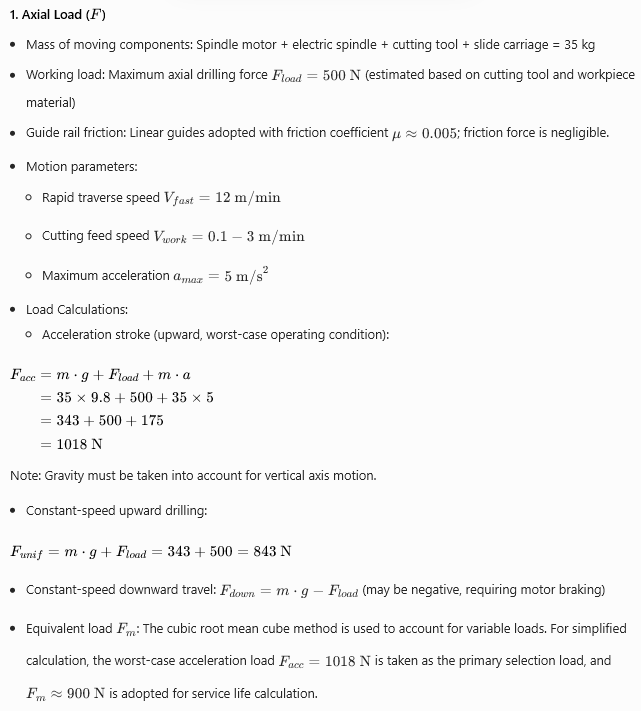

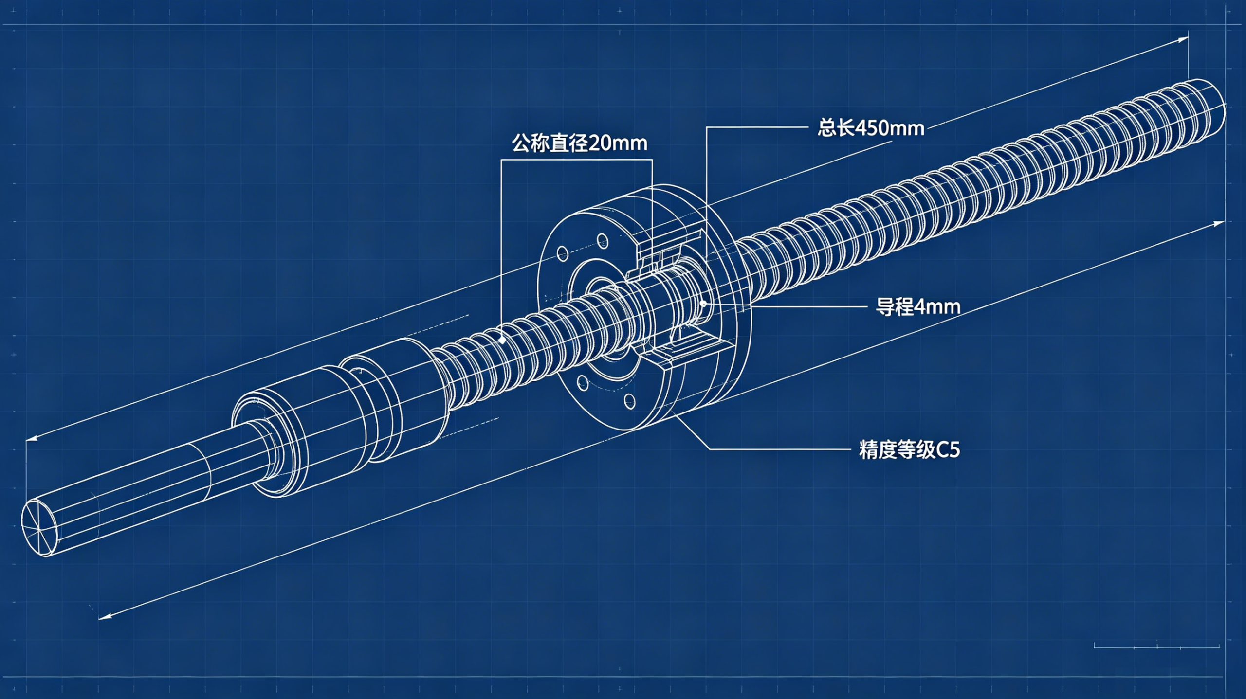
3.Travel Length (L): Effective travel = 300 mm.The overall screw length shall reserve allowance for nut travel and support margins at both ends, preliminarily estimated as 450 mm.
4.Accuracy Requirements:
Positioning accuracy: ±0.01 mm per 300 mm travel
Repeat positioning accuracy: ±0.005 mm
According to manufacturer catalogs, C5 grade ball screw can meet the above requirements (standard precision grade for general CNC equipment).
5.Service Life (Lh): Target service life is 20,000 hours.
6.Mounting Method: Vertical installation with motor mounted on the top.To avoid screw deflection caused by self-weight and working load and improve rigidity, fixed-supported (FK) mounting configuration is adopted.
Fixed end (motor side): Angular contact bearing assembly is applied to bear both axial and radial loads.
Supported end (bottom side): Deep groove ball bearing is used, which only carries radial load and allows slight axial thermal expansion.
7.Operating Environment: Minor splashing of cutting fluid and aluminum chips exists, so sealed nuts with wipers and protective covers are required.
2: Preliminary Selection of Ball Screw Parameters
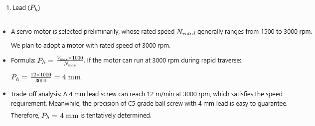
2.Accuracy Grade: As mentioned above, C5 grade is selected.
3.Nut Type: Double-nut preloaded type is selected to achieve zero backlash and high rigidity.
3: Preliminary Dimension Selection Based on Axial Load and Service Life
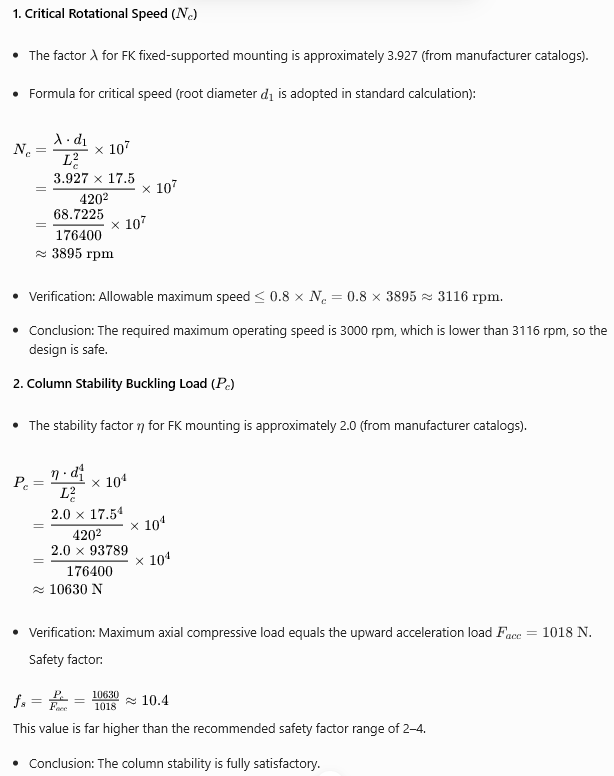
4: Check Critical Rotational Speed and Column Stability
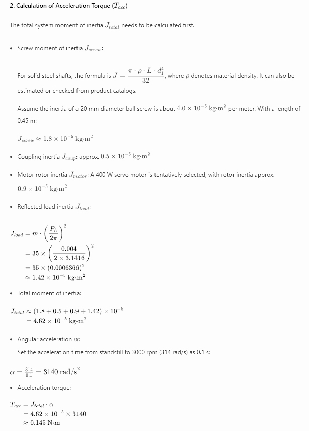
5: Calculation of Driving Torque and Motor Power

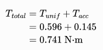
3.Total Required Torque
4.Motor Selection

6: Final Determination and Selection of Auxiliary Components
1. Final Ball Screw Model
(Example): FDI 2004-4 B0 C5 ZA3
– FDI: Double preloaded nut ball screw
– 20: Nominal diameter 20 mm
– 04: Lead 4 mm
– 4: Nut circulation code
– B0: Preload level (medium preload)
– C5: Precision grade
– ZA3: Shaft end machining style (customized according to mounting requirements)
– Overall length: 450 mm
2. Selection of Auxiliary Components
– Support bearings (fixed end): Matched DB pair angular contact ball bearings dedicated for ball screws, model 7204 BEP.
– Support bearings (supported end): Deep groove ball bearing model 6004.
– Coupling: Diaphragm coupling with rated torque over 2.5 N·m, bore size matched to motor shaft and screw shaft.
– Lubrication: Lithium-based grease; the nut is equipped with an integrated grease fitting.
– Dust protection: Built-in wiper seal on the nut, plus an additional flexible telescopic cover for the screw shaft.
Case Summary
Through the above steps, we have selected the following components for the Z-axis:
– Ball screw: Nominal diameter 20 mm, lead 4 mm, C5 precision grade, double preloaded nut type, overall length 450 mm.
– Servo motor: 400 W servo motor with rated speed of 3000 rpm.
– Bearings: Matched angular contact bearing set for fixed end, deep groove ball bearing for supported end.
This selection satisfies all requirements in terms of speed, precision, service life and rigidity. After verification of critical rotational speed and column stability, it delivers a safe, reliable and cost-effective solution. In practical projects, these parameters can be submitted to suppliers for final confirmation and quotation.


Add comment