

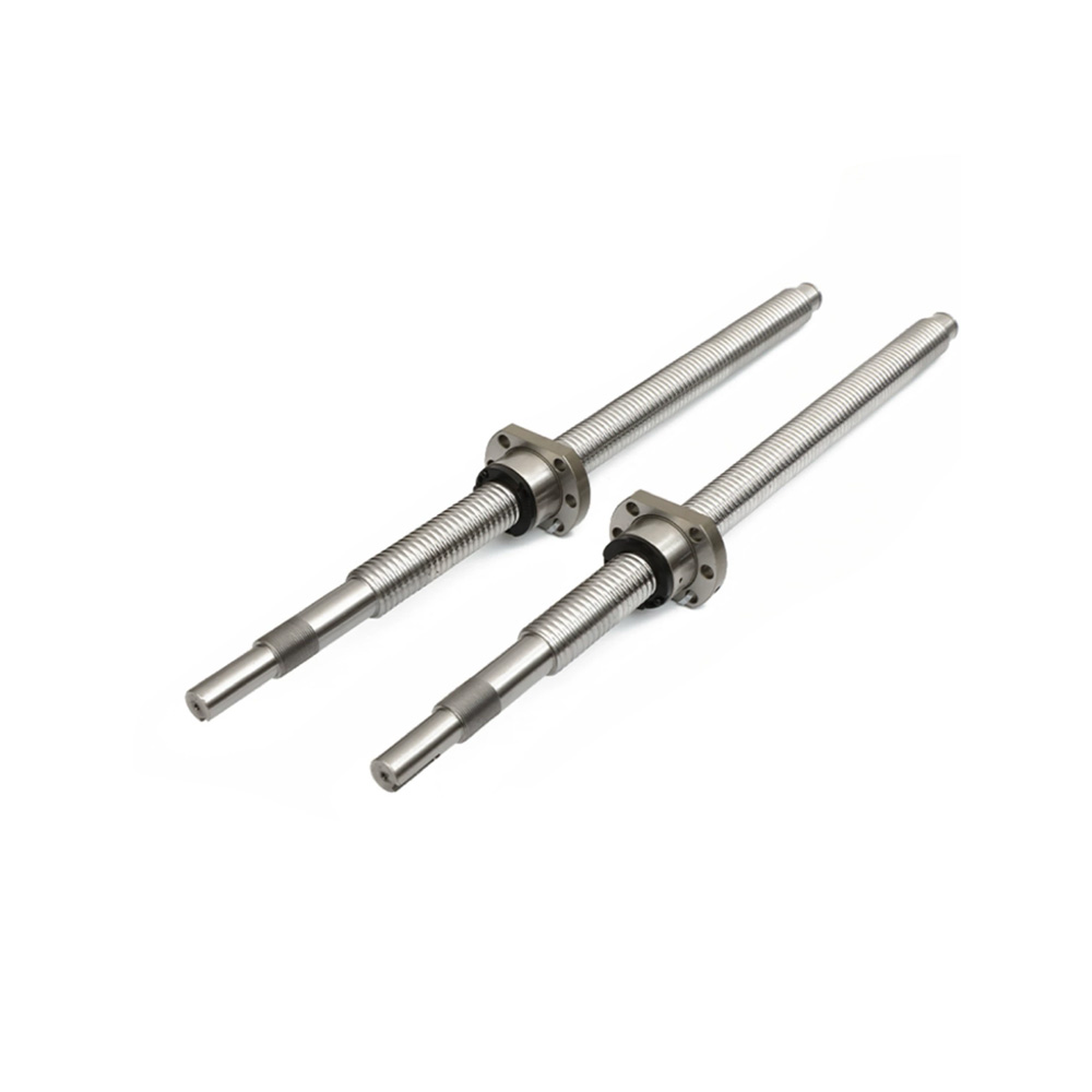
Complete Ball Screw Selection & Calculation Guide for Mechanical Design
Ball Screw Selection & Calculation Made Easy
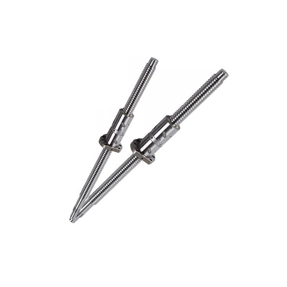
1.Structure of Ball Screw
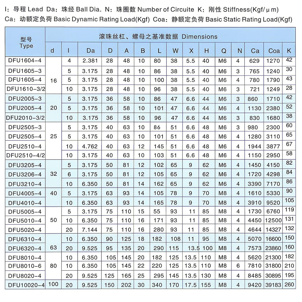
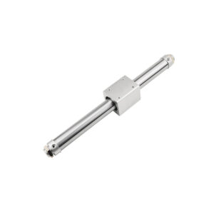
The ball screw is generally composed of a screw shaft, nut, steel balls and seals.
2.Classification of Ball Screws
They fall into two main types: rolled ball screws for transmission applications, and precision ball screws for positioning.
3.Accuracy of Ball Screws
Rolled ball screws for transmission adopt accuracy grades C7 and C10.
Precision ball screws for positioning use grades C0, C1, C2, C3 and C5.
The length variation of ball screws is generally defined per 300 mm.
For example, the typical accuracy of C7 ball screw is ±50 μm/300 mm.
4.Ball Circulation Types of Screw Nut
They are divided into internal circulation and external circulation. Internal circulation includes floating type and fixed type; external circulation consists of tube insert type and spiral groove type.
The internal circulation features the shortest ball circulation path, flexible reversing, compact structure, high rigidity and reliable performance with long service life. It has a small outer diameter of the nut assembly and low friction torque, making it suitable for various feed and positioning systems requiring high sensitivity, high precision and high stiffness.
The external circulation has a longer ball circulation path, yet it is compact in axial arrangement with small axial dimension. Its nut assembly has a relatively large outer diameter (Type C is smaller) and lower rigidity, while the balls run smoothly with good flexibility and light operation.
The tube insert type delivers low friction torque, ideal for medium-load, high-speed motion and precision positioning systems, and it shows unique advantages for large lead and multi-start threads.
The spiral groove type generates higher friction torque. It is applied to general engineering machinery and not suitable for transmission systems that demand high rigidity and high-speed operation.
5.Mounting Methods of Ball Screws
(1) Fixed at one end, free at the other (G-Z type)
This mounting style features a simple structure, but with low axial rigidity and critical speed. It is applied to short-stroke and vertical transmission. The fixed end is generally fitted with angular contact thrust ball bearings or needle roller thrust cylindrical roller bearings that can bear bidirectional axial loads and radial loads, with axial preloading applied. The free end is completely unrestrained without any support.
(2) Fixed at one end, supported at the other (G-J type)
It is the most typical and widely used mounting method for ball screw mechanisms, suitable for working conditions with medium speed, high rigidity and high precision. The fixed end bears both axial and radial loads, while the supported end only carries radial loads and allows slight axial float. This design reduces or prevents bending caused by the screw’s self-weight, and enables the screw to elongate freely at one end when thermal deformation occurs.
(3) Fixed at both ends (G-G type)
This style is used for long screws, high-speed operation and applications requiring high tensile and compressive rigidity. Both ends are equipped with angular contact thrust ball bearings or needle roller thrust cylindrical roller bearings capable of bearing bidirectional axial loads and radial loads, along with preloading. It effectively enhances the support rigidity of the screw and partially compensates for thermal deformation.
(4) Supported at both ends (J-J type)
It has a simple structure. However, since the supporting ends only withstand radial loads, thermal elongation of the screw will affect machining accuracy. Therefore, it is suitable for equipment with medium rotating speed and moderate precision requirements.
6.Preload Methods of Ball Screws
Ball screws mainly adopt the following preload methods:
Double Nut Shim Preload
Preload is achieved by adjusting the thickness of the shim between two nuts. It features simple structure and high rigidity, yet the adjustment process is cumbersome and requires repeated disassembly and shim trimming.
Double Nut Thread Preload
Preload is realized by rotating the threaded structure to adjust the gap between two nuts. This method allows adjustable preload force and delivers high precision. However, periodic maintenance is required, and re-adjustment may be needed due to loosening after long-term operation.
Single Nut Offset Lead Preload
Preload is generated by a tiny offset of the raceway lead inside the nut. It has a compact structure and requires no further adjustment, but it involves complex manufacturing and higher costs.
Oversized Ball Preload
Steel balls slightly larger than the raceway are adopted to create preload via interference fit. It provides uniform preload force with no extra components. Excessive interference will accelerate wear and shorten service life.
Integral Nut Variable Pitch Preload
Preload is produced by slightly changing the pitch of a single nut. It is suitable for applications with general preload requirements.
Double Nut Pin Fastening Preload
Two nuts are used, and preload is generated and maintained by positioning pins. This design applies to scenarios that require the rotating torque to be kept to a minimum.
Double Nut Spring Preload
Springs are installed between two nuts to apply preload. It is ideal for working conditions where rotating torque needs to be maintained at the lowest level.
The characteristics and applicable scenarios of each preload method are as follows:
Double Nut Shim Preload
Simple structure and high rigidity, but troublesome to adjust. Suitable for applications requiring infrequent adjustment.
Double Nut Thread Preload
Adjustable preload force and high precision. Periodic maintenance is needed. Ideal for scenarios requiring high-precision tuning.
Single Nut Offset Lead Preload
Compact structure with no adjustment required. It features complex production and high cost, and applies to high-precision applications with rare adjustments.
Oversized Ball Preload
Uniform preload force without additional components. It suffers from fast wear and short service life, fit for medium and low load conditions.
Integral Nut Variable Pitch Preload
Simple structure, easy adjustment, and suitable for general preload requirements.
Double Nut Pin Fastening Preload
Designed for applications where rotating torque must be kept to a minimum.
Double Nut Spring Preload
Simple structure and easy adjustment, suitable for scenarios requiring minimum rotating torque.
7.Advantages of Ball Screws
- Low friction coefficient, small driving torque and high efficiency.
- Capable of maintaining high precision.
- Supports micro-feed movement.
- No lost motion and high rigidity.
- Enables high-speed feed.
- Low heat generation.
8.Ball Screw Selection Calculation
Given: maximum output speed of drive mechanism n, linear velocity V, service life Lh, acceleration time t1, deceleration time t2, constant-speed time t3, total load mass m, friction coefficient μ, nut length Lnut, shaft end dimension Lshaft, maximum required stroke Lmax, screw diameter d, screw root diameter d1, distance between load acting points on screw l, screw support span l2, limiting speed of nut Nlim, external force F, total moment of inertia of mechanism J, angular acceleration α.
1.Calculate the lead:
Plead≥60V/n (mm)
2.Select the nut
Assume the analysis is based on a four-cycle acceleration-deceleration trapezoidal motion profile.
Acceleration: a=V/t1
During acceleration, axial load: Pa=μmg+ma
During constant speed, axial load: Pb=μmg
During deceleration, axial load: Pc=ma−μmg
Total operating time for four cycles: ttotal=4(t1+t2+t3)
Assume total time of four cycles including dwell time: ttotal(inc)
Average speed under acceleration/deceleration mode: N1=n/2
Average speed under constant speed mode: N2=n
Calculate the average axial load: Pm=

Calculate the average rotational speed: Nm=
Operating factor fw (1.2~1.5 for normal operation, 1.5~2 for impact conditions)
Calculate the net operating life: Lho=Lh×(ttotal/ttotal(inc))
Finally, calculate the basic dynamic load rating: C=
3.Accuracy Selection
First, select an accuracy grade higher than the required level. In addition, the axial clearance shall be smaller than the repetitive positioning accuracy.
4.Screw Shaft Selection
(a) Screw Shaft Length
The general margin is 1.5 to 2 times the lead.
Margin length: Lmar=2×1.5×Plead (both sides)
Total screw length: Lscrew=Lmar+Lmax+Lnut+Lshaft
Check the length-diameter ratio: Lscrew/d≤60
(b) Allowable Axial Load Verification
The coefficient is determined by the mounting type of the ball screw.
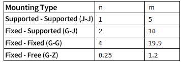
Calculate the allowable axial load using the formula: Pallow=
Require Pallow>Pa
(c) Allowable Speed Verification
The relevant coefficient is determined by the ball screw mounting type.
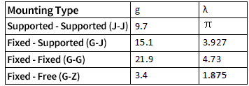
Calculate the allowable speed according to the formula:
Nc=
Require Nc>n
(d) Ball Nut Limit Speed Verification
Table of coefficient A
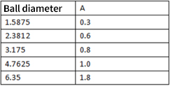
Calculate DmN=(d+Factor A)×n
DmN≤Nlim
(5) Drive Motor Verification
(a) Load Torque T1
T1=2πημmg⋅Plead, η=0.9
(b) External Force Torque T2
T2=2πηF⋅Plead
(c) Acceleration Torque T3
T3=Jα
Total motor output torque:
T=(T1+T2+T3)×Safety Factor




Add comment